Download
1 / 17
200 likes | 423 Views
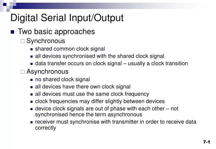
Digital Serial Input/Output. Two basic approaches Synchronous shared common clock signal all devices synchronised with the shared clock signal data transfer occurs on clock signal – usually a clock transition Asynchronous no shared clock signal all devices have there own clock signal

E N D
Digital Serial Input/Output • Two basic approaches • Synchronous • shared common clock signal • all devices synchronised with the shared clock signal • data transfer occurs on clock signal – usually a clock transition • Asynchronous • no shared clock signal • all devices have there own clock signal • all devices must use the same clock frequency • clock frequencies may differ slightly between devices • device clock signals are out of phase with each other – not synchronised hence the term asynchronous • receiver must synchronise with transmitter in order to receive data correctly
Serial I/O configurations and standards • Simple point to point communications – e.g. RS232, RS423 and RS422. • Bus based with • one master and one or more slaves e.g • RS485 • SPI(Serial Peripheral Interface) bus – Serial data out, serial data in and serial clock) • I2C (Inter-IC bus) • Universal Serial Bus (USB) • multiple masters and one or more slaves e.g. I2C bus • Peer to peer arrangement e.g. CAN(Control Area Network) bus
Baud Rate • Baud rate defines the switching speed of a signal (i.e. the Baud rate indicates how often a signal changes state). • Bit rate defines the rate at which information flows across a data link. measured in bits/second(bps) • For a binary two-level signal, a data rate of one bit per second is equivalent to one Baud 11 Data 10 Bit rate = 2 x Baud rate 01 00 Time 00 01 11 10 11 00 01 Note: For a binary signal Baud rate = bit rate = 1/bit time
Universal Asynchronous Receiver/Transmitter(UART) • Most UARTS are full duplex – they have separate pins and electronic hardware for the transmitter and receiver that allows serial output and serial input to take place in parallel • Based around shift registers and a clock signal. • UART clock determines baud rate • UART frames the data bits with • a start bit to provide synchronisation to the receiver • one or more (usually one) stop bits to signal end of data • Most UARTs can also optionally generate parity bits on transmission and parity checking on reception to provide simple error detection. • UART often have receive and transmit buffers as well as the serial shift registers
Status information Parallel data Serial output UART Clock from baud rate generator UART - Transmitter • Transmitter (Tx) - converts data from parallel to serial format • inserts start and stop bits • calculates and inserts parity bit if required • output bit rate is determined by the UART clock
Status information Serial input Parallel data UART Clock from baud rate generator UART - Receiver • converts serial format back to parallel data • Rx synchronises with transmitter using the start bit • samples data line at UART clock rate (normally a multiple of baud rate, typically 16) • reads value in middle of bit period (Infineon 167 uses a majority decision of the 7th, 8th and 9th sample to determine the effective bit value. • calculates parity and checks against received parity bit
Asynchronous serial reception Idle etc. Start bit waiting for start bit 1 First data bit Start detected 0
Asynchronous • Usually used on simple systems • Typically point to point • Various different formats and protocols • Normally 8bit data format with one start and one stop bit • Standards: E.g. RS232 – • defines connector type, pin assignments, voltage levels, max bit rate, cable length etc. • Min. 3 pins – TxD, RxD, Ground • Other pins for data flow control. • Some common baud rates - 300,1200,9600,19200
ASC0 Baud Rate Generation • The serial channel ASC0 has its own dedicated 13-bit baud rate generator; basically a timer with reload capability. • The baud rate generator is clocked with the CPU clock divided by 2 (f CPU /2). • The timer counts downwards and can be started or stopped through the Baud Rate Generator Run Bit S0R in register S0CON. Each underflow of the timer provides one clock pulse to the serial channel. The timer is reloaded with the value stored in its 13-bit reload register each time it underflows. • The resulting clock is then divided according to the operating mode and controlled by the Baudrate Selection Bit S0BRS. If S0BRS = ‘1’, the clock signal is additionally divided to 2/3rd of its frequency (see formulas and table).
ASC0 Baud Rate Generation contd. • So the baud rate of ASC0 is determined by the CPU clock, the reload value, the value of S0BRS and the operating mode (asynchronous or synchronous).
Infineon 167 - ASC0 Initialisation // This is zero 0, this is 'Oh' O //initialise serial port to 9600 baud void serial_init() { P3 |= 0x0400; // SET PORT 3.10 OUTPUT LATCH (TXD) DP3 |= 0x0400; // SET PORT 3.10 DIRECTION (TXD OUTPUT) DP3 &= 0xF7FF; // RESET PORT 3.11 DIRECTION (RXD INPUT) S0TIC = 0x80; // SET TRANSMIT INTERRUPT FLAG S0RIC = 0x00; // RESET RECEIVE INTERRUPT FLAG S0BG = 0x40; // SET BAUDRATE TO 9600 BAUD S0CON = 0x8011; // SET SERIAL MODE } NOTE: The Keil 166 C compiler standard I/O functions use the ASC0 serial port i.e printf,putchar,scanf etc. will use ASC0. But the user program MUST initialise the ASC0 before any of the functions can be used.
User functions for simple polled serial I/O char getbyte (void) { char c; while (S0RIR==0); // or while(!S0RIR) c = S0RBUF; S0RIR = 0; return (c); } void putbyte (signed char c) { while (!S0TIR); S0TIR = 0; S0TBUF = c; }