Download
1 / 30
300 likes | 430 Views
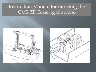
CMS ZDC Remote Handling Tool (ZDC Crane) Force Calculations and Mechanical Analysis Calculations of Driveline loads and forces FEA reports of Structural Components. P. Debbins University of Iowa May 12, 2014. CMS ZDC Remote Handling Tool (ZDC Crane).

E N D
CMS ZDC Remote Handling Tool (ZDC Crane) Force Calculations and Mechanical Analysis Calculations of Driveline loads and forces FEA reports of Structural Components P. Debbins University of Iowa May 12, 2014
CMS ZDC Remote Handling Tool (ZDC Crane) Calculations of Normal operating forces for worst-case Payload (Stainless Bars) present in the movement drivelines. Actuator jack loading and input drive forces: M1 (Vertical Axis) Driveline M3 (Rotational Axis) Driveline Bearing loading in jointed structures. Listing of Component specifications Calculation of Stress levels and safety factors The reader of this document should be familiar with the document: CMS ZDC Crane Structural Assembly Reference
Force Analysis of Actuators-Drivelines-Motors Calculation of Working Loads Worst case load is Stainless Bars Rotary Axis: 2 x Merkur M3 Actuators. Suspended load on rotary system. This Is NOT the direct load applied to actuators Vertical Axis: 2 x Merkur M1 Actuators: Lift vertically (against Gravity) at Arrows Center of Gravity of SS Bars offset from Crane centerline: imbalances Actuator loading +/- 3% 100kg total (3 pieces) 60 kg 60kg 316 kg 58 kg 316 kg 58 kg 434 kg = 4256N 534 kg = 5236N Each actuator : (4256N / 2) = 2128N Add 5% for imbalance: M1 actuator load = 2235N for Each M1 actuator. The suspended load is coupled to M3 Actuators via a rotary-linear crank Mechanism. Calculation of the actuator Loading follows in a later section of this Document.
Calculations for M1 (Vertical Axis) Driveline Exploded view and component listing 3 2 3 1 1 4 5 • Pfaff-SilberblauMerkur M1 Type2 jack • R+W Line shaft: EZ2/10/948/B/10PFN/10PFN • R+W Coupling: EKL/5 + 10mm shaft (one side) • R+W Torque limiter: ES2/5 (A) (W) 3 – 6Nm • Baldor Servo Motor: BSM63N-375AA
Component Specifications and Calculations of Drive parameters 1: Pfaff-SilberblauMerkur M1 Type2 (traveling Nut) Maximum Lift = 5kN (ZDC tool requires max. 2235N) Safety Factor = 2.24. Lift is tension only, no buckling forces Low gear ratio (16:1) Maximum input shaft speed = 1500rpm (ZDC tool operates at 1000) Maximum input shaft torque = 3,4Nm (Torque limiter set at 3,2Nm) Input shaft torque to lift 2,5kN @ 1000rpm = 0,4Nm (for each M1 Actuator) Stainless steel screw, Bronze EFM type traveling nut Low ratio lifts 0,25mm / input revolution> @1000rpm input lift = 250mm / min. Total lifting time for tool to raise or lower payload vertically = 2:28 min. 2: R+W EZ2/10/948/B/10PFN/10PFN Line Shaft Rated torque = 12,5Nm (Torque limiter set to 3,2Nm) Safety factor = 3.9 Critical Speed = 2707 rpm (line shaft operated at 1000) Line shaft coupling is with keyway to positively mechanically index twin M1 actuators 3: R+W EKL / 5 coupling Rated torque = 12Nm
4: R+W Torque Limiter ES2/5/A/W/10/11/3,2/3-6 Disengagement torque set 3,2Nm (M1 actuator input max = 3,4Nm) Limiter reengages automatically when overload is removed. Operating input torque of ZDC M1 (vertical) drive line is ~ 1,2Nm (both actuators together). Limiter only engages in case of mechanical jamb, protecting all drive components against excessive force input. (M1 Driveline motor peak torque (3 sec) = 8,36Nm) 5: Baldor Servo Motor BSM63N-375AA Continuous stall torque = 2,09Nm @ 2,82A current Peak torque = 8,36Nm @ 10,1A current Max speed 7000 rpm (motor operated at 1000rpm)
Operational testing of M1 (vertical axis) driveline Operating the crane has shown the M1 (vertical) driveline to require a total Input of 1,2Nm to drive both M1 actuators lifting a load (together) of 487kg. This is using the Test Payload which is heavier ~12% than the stainless steel bars Which are the worst case intended operation. All driveline components and motor are operating well within their ratings and safety Factors are high. System is mechanically torque limited to 3,2 Nm (3,4 Nm torque input to M1 actuators is The weakest part of the driveline).
M3 Actuator screw loading calculation Calculation of M3 jack screw load. Screw load depends on position of System in rotation. 3 positions of crane are illustrated: maximum extension To Sarco (#1), Maximum vertical (centered over pivot point) (#2), and full Retraction centered over TAN (#3) #2 #1 #3 F=0 5236N 5236N 5236N Full Rotational Retraction (Centered over TAN). Maximum Compression Load on actuator. Vertically centered over Pivot point – zero load to Actuator. Full Rotational Extension (Centered over Sarco).Maximum Tension load to actuator.
Dynamic Simulation – Computation of spindle load – full motion range #3 #2 #1 2750N Total suspended load = 5236N (5236N / 2) = 2618N Add 5% for imbalance: Each M3 actuator must Apply force to rotate a suspended load of 2750N Force Graph Pos #1 Absolute max load: 10266N Tension Pos #2 No load on M3 spindle Pos #3 Max Compression (Buckling) load: 2352N
Calculations for M3 (Rotational Axis) Driveline 3 2 6 5 4 1 1 7 1: Pfaff-SilberblauMerkur M3 Type 1 jack 2: R+W Line shaft EZ2/20/1152/B/16PFN/16PFN 3: R+W Coupling: EKL/10 4: R+W Torque Limiter: ES2/10/A/W/16/20/8,3/4-12 5: Stainless Steel shaft adapter 6: FennerTrantorque GT keyless bushing 7: Baldor Servo Motor: BSM90C-3150AA
1: Pfaff-SilberBlauMerkur M3 Type 1 Maximum Allowable Compression load Of Actuator Screw is a function Of extension length The Case for CMS ZDC Tool is Euler II Factory charts show for M3 With 30x6Tr screw Euler case II 2500N permissible buckling force is Allowed up to 1400mm extension. The ZDC tool M3 actuator experiences 2352N buckling force at Extension length = 35mm Buckling force diminishes to 0 at Extension 120mm, where for all Further extension it becomes a tension Load. Max tension load experienced = 10,27kN M3 allowable tension = 25kN Safety Factor = 2.4 (under tension)
1: Pfaff-SilberBlauMerkur M3 Type 1 Maximum Lift = 25kN (ZDC tool requires 10266N tension max) Safety Factor = 2.4 under tension Buckling force loads are trivial with respect to the M3 specifications Low Gear ratio (24:1) Maximum input shaft speed = 1500rpm (M3 driveline operates at 1000rpm Maximum input shaft torque = 18Nm (R+W torque limiter set at 8,3 Nm) Input shaft torque to lift 10kN @ 1000rpm = 2,1Nm (for each M3 Actuator) Low ratio lifts 0,25mm / input revolution : @1000rpm input: Lift = 250mm / min. Total time for Tool to fully move between TAN and SARCO positions = 2:43 min. 2: R+W EZ2/20 Line Shaft Rated Torque = 17Nm (Torque limiter set to 8,3Nm) Safety Factor = 2 Critical Speed = 2406 rpm (System operated at 1000 rpm) Line shaft coupling is with Keyway to positively mechanically index twin M3 actuators 3: R+W EKL / 10 Coupling Rated Torque = 16Nm
4: R+W Torque Limiter ES2/10/A/W/16/20/8,3/4-12 Disengagement torque = 8,3Nm. Operating input torque to M3 driveline is ~ 5Nm (both actuators operating at worst case loading position) Torque limiter reengages automatically when overload is removed. Limiter only operates in case of Mechanical jamming, to protect all driveline components from damaging overloads in event of mechanical Jam. M3 driveline motor peak torque = 23,4Nm (3 sec) 5: Shaft Adaptor. Custom part. Consult the document: CMS_ZDC_Crane_Mech_Structures(1).pdf 6: FennerTrantorque GT 6202820 24mmx45mm Maximum holding torque = 380 Nm
7: Baldor Servo Motor BSM90C-3150AA Continuous stall torque = 7,8 Nm @ 6,0 A current Peak torque = 23.4 Nm @ 15,4 A current Max speed 5000 rpm (motor operated at 1000 rpm)
FEA Calculations Components Naming Overhead Beam Sidewall Sidewall Carrier Beam Lifting Bridges Lifting Lugs EM Bars HAD Bars
FEA of Lifting Bridge Components Force Loading FEA Simulation modeled in static equilibrium with Forces applied at bolts (shown in arrows) and at Surface of pin contact to shoe or foot. HAD Type 4x bridges carry 335kg 84kg / ea. bridge 1x (Nominal) and 3x overload considered EM Type 2x bridges carry 68kg 34kg / ea. bridge Interconnect Pin 84kg (Nom Load) 840N 252kg (3x overload) 2520N 34kg (Nom. Load) 340N 102kg (3X overload) 1020N
FEA result: HAD type “foot” and “shoe” All lifting bridge components are minimally stressed (safety factor > 15) Results are posted at links below: Hadronic Foot : Hadronic Foot FEA Hadronic Shoe : Hadronic_Shoe_FEA EM Foot : EM_Foot_FEA EM Shoe : EM_Shoe_FEA
Carrier Beam FEA F(Had) F(em) M10 x 90 hex bolt (8,8) Fixed constraint (M1 traveling nut) 840N (1x) 2520N (3x) 4 places F(em) = 180N each bolt (4 places) 1x loading 540N each bolt (4 places) 3x overload. 340N (1x) 1020N (3x) 2 places F(Had) = 430N each bolt (8 places) 1x loading 1290N each bolt (8 places) 3x overload Carrier Beam FEA reports posted: Carrier_Beam_FEA
Overhead Beam FEA Overhead Beam F = 2235N (2 places) Nom. loading 6705N (2 places) 3x overload Fixed Constraint Fixed Constraint With imbalanced load each M1 actuator is modeled to carry 2235N FEA Results posted: Overhead_Beam_FEA
Sidewall FEA and force modeling is here 54N 0.71 deg. Offset from vertical creates a sideways (along Z axis) thrust of suspended payload. 0.71 deg. angle of 4256 suspended load results In 54N thrust in Z. 2445N – Combined 2235N of M1 actuator and Overhead masses Fixed Constraint 54N Sidewall FEA posted : Sidewall FEA
Rotary System components naming M3 Actuator Swivel Mount Rotary Arm Pivot Mount
Calculation of Forces in Rotary System Rotary arms, bearings, Pivot and Swivel Mounts
Bearing Loadings 3 All Actuators and Bearings are lubricated With DupontKrytox 227 Radiation Resisting Grease See Mechanical Reference For Radiation Testing Data And Specifications 4 1 2 1: 2x SKF 32005 X/Q Taper Roller Bearings. Nominal load = 2750N (per 2 bearings) 2: 2x SKF 32005 X/Q Taper Roller Bearings. Nominal load varies with rotary position. Worst-case load = 10855N (per 2 bearings) 3: 1x SKF 22205 E Spherical Roller Bearing. Nominal load varies with rotary positon. Worst-case load = 10266N. This bearing isolates the M3 spindle from side loading by any misalignment and/or deflection of the rotary arm. 4: 2x SKF NA 4905 Needle Roller Bearing. Nominal load varies with rotary position. Worst-case load = 10266 (per two bearings)
FEA of Rotary Arms Forces present on each Rotary Arm 2750N force represents +5% from Nominal to provide worst-case 33N 33N 5236N total suspended load FEA input forces: 2750N (1x) and 8250 (3x overload) 50N (1x) and 150N (3x overload) for Z axis thrust. 2750N 2750N 0.71deg offset in Z direction results in 33N thrust per arm
FEA Results Postings: Rotary Arms: 1x loading: Rotary Arm (1x loading) 3x loading: Rotary Arm (3x loading) Pivot Mount: 3x loading: Pivot Mount (3x loading) Swivel Mount: 3x loading: Swivel Mount (3x loading)