Download
1 / 73
730 likes | 736 Views
Improvements to 802.11 for Video Applications. Date: 2007-10-29. Authors:. Abstract. The possible impairments that jeopardize the user experience when using video over 802.11 are investigated The Video Problem The RF Problem QoS OBSS DLS 11n

E N D
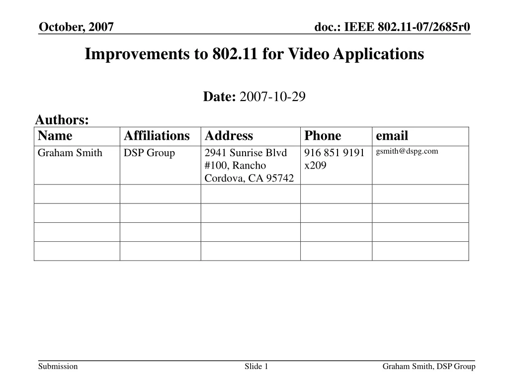
Improvements to 802.11 for Video Applications Date: 2007-10-29 Authors: Graham Smith, DSP Group
Abstract • The possible impairments that jeopardize the user experience when using video over 802.11 are investigated • The Video Problem • The RF Problem • QoS • OBSS • DLS • 11n • Methods or options that could improve the experience are introduced and discussed • Recommendations are made for future 802.11 amendments that might be useful Graham Smith, DSP Group
Objectives The objectives are To investigate the possible impairments that jeopardize the user experience when using video over 802.11 Look into methods or options that could improve the experience Future 802.11 amendments that might be useful and their impact Graham Smith, DSP Group
CONTENTS • The Video Problem • The RF Problem • QoS • OBSS • DLS • 11n • Recommendations Graham Smith, DSP Group
Video Problem What problems have existed that have caused user dissatisfaction? When considering video streaming, the required data rates are in the range 1 to 23Mbps. Practical range of 802.11a/g Video products, using of MPEG 4/H.264 Graham Smith, DSP Group
Video – Effect of Lost Packet • Effect of Packet Loss on Video • A video MSDU contains 7 x 188 video octets, or 10,528 ‘video’ bits. • One packet is lost, then 10,528 bits are lost. • Examples: • TV (PAL) 750 x 560 = 420,000 pixels, Frame rate of 30 fps • TV = 12.6M Pixels/sec • SDTV at 8Mbps, then 1 bit = 12.6/8 = 1.6 pixels • Hence, if one packet is lost • 10528 bits = 16582 pixels = 16582/750 = 22 lines LOST • HD 1920 x 1080 = 2,073,600 pixels • HD = 62.2M Pixels/sec • HDTV at 20Mbps, • 1 lost packet is a minimum of 19 lines lost • Losing a minimum of 19-22 lines will definitely cause an observable video error!! • Packet Loss possible because of limit on # of re-tries. Graham Smith, DSP Group
Video Errors Packet Loss 0.1% gives 44 Errors per minute Graham Smith, DSP Group
Concatenated Coding for VideoHigher Layer SolutionBasic Methodology • To allow video coding, MAC changes required • Might allow low packet loss over PHY c.f. zero Graham Smith, DSP Group
R-S Concatenated Coding Packet Loss is the concern. Improved with retries Graham Smith, DSP Group
RS Coding Theoretical Improvement 2.5 errors per hour cf 44 errors per minute FEC at Application Layer potentially offers significant improvement Graham Smith, DSP Group
FEC Coding at Application Layer Looks attractive, other technologies do it. Task is to see what changes are necessary to allow it. • Headers • Encryption • Retry Mechanism • Indication that Stream is using FEC Graham Smith, DSP Group
FEC at Application Layer • Headers • Transport Layer • LLC Header, 8 Bytes, no checksum (CRC on complete frame)Need to add a checksum? • UDP Header, 8 Bytes including checksum for complete frame“UDP Lite” has been proposed that has checksum on Header only • Network Layer • IP Header, 20 Bytes with Header Checksum • RTP Header, 12 Bytes no checksum (included in UDP checksum)Need to introduce RTP Header Checksum? • Is this out-of-scope? Must be implemented. Graham Smith, DSP Group
FEC at Application Layer • Encryption • Decryption will add more errors to the data, if errors in data • Video data could/should be encrypted at the Application Layer for DRM purposes(?) • Reasonable case to send video without encryption on 802.11 • Need to ‘flag’ the video data in order to allow this in a network that is using encryption. • Allowing different encryption for different transmissions needs to be solved. Graham Smith, DSP Group
FEC at Application Layer • Retry Mechanism • If FCS error, no immediate ACK is sent • Transmitter sends an immediate “Retry” • If “Headers” check out, then • ACK is sent to stop more Retries • If a retry is received with no FCS error, then this should replace previous • Otherwise proceed with first (or subsequent) and present data to Application Layer • If “Headers” do not check out, then, • Dump data and look at subsequent retries Graham Smith, DSP Group
FEC at Application Layer • Need to indicate to receiver (and AP if it is transferring the stream) that “FEC Stream” is in use • Video streams should be using EDCA Admission Control or HCCA and hence should be setting up a TSPEC. • TSPEC could be used to • Request ability to send “FEC Video” • Send without encryption • IE required to indicate ability of an AP or STA to support “FEC Video” Graham Smith, DSP Group
Video • To support the upper layer use of extra coding, however, does require changes in the Layer 2. • Ability to pass up packets with data errors • Extra control of re-tries • Possible ability to identify video traffic that is not encrypted at Layer 2. • For purely Layer 2 considerations the need for zero or very low packet loss and controlled latency requires: • A good PHY with good diversity to overcome dynamic multi-path • The inclusion of Wi-Fi MAC necessary buffers and processor speed, i.e. a Wi-Fi device that is designed for the application[1] And very important: • The use of an effective QoS scheme so as to guarantee the required latency and throughput • [1]We do not refer here to the video buffers used by the codec. We refer to the need for the MAC to have sufficient buffers to handle the packets as they are presented or passed to the upper layers. Graham Smith, DSP Group
RF Problem Not a MAC Problem, but interesting to note. Will skip quickly through this Graham Smith, DSP Group
Need for Good PHY - the RF Problem Multiple signals arrive at receiver with differing amplitudes and phases Here shown are the “first order” paths, “single bounce” Graham Smith, DSP Group
Signal Strength – 12 x 12 room 2437MHz 10 -15dB variations over very short distances. Caused by multi-path Peak to trough in 1½ inches Peak to trough in 2/3 inch Graham Smith, DSP Group
Indoor Testing • Formula used to predict the mean signal strength at any point in the building/house The average error was +1.57dB and the standard deviation of the error was 4.45dB Graham Smith, DSP Group
Indoor Testing 11 The STA was swung through a small arc of about 2 feet at a rate of about 2 feet per second Note that this is the total signal strength. Even selected antenna shows variations of >10dB, no better than each antenna, but the selected signal strength is higher. Note the change in signal strength over very short distances. This can only predict the mean data rate, it does not show the effects of multi-path fading. Graham Smith, DSP Group
Selective Fading of sub-carriers • Received signal is effected by: • Diversity • Delay spread (up to 50ns for a home) • Position • Frequency • Room size • For example, frequency and OFDM Sub Carriers • Both antennas can be faded • Combined diversity, on sub carrier basis (MRC) performs better And these are just for simple open room with no furniture or other reflecting surfaces! For zero or very low Packet Error Rate, good Diversity required Part Explanation of why poor Video in past is that almost all Wi-Fi Cards used switched antenna diversity 802.11n Devices do have good diversity Graham Smith, DSP Group
Video needs QoS Problem is that 802.11 is designed as a Contention Based Scheme Graham Smith, DSP Group
Introduction - EDCA EDCA is a priority based QoS and four Access Categories (AC) are used: • AC_VO the highest priority. Also referred to as ACI 11 (Access Category Index). • AC_VI (ACI 01) is the second highest priority. • AC_BE (ACI 00) is the third highest priority. • AC_BK (ACI 01) is the lowest priority. • EDCA priorities are realized by setting the parameters of the contention functions, CWmin, CWmax, and AIFSN. Graham Smith, DSP Group
Introduction - HCCA HCCA is a scheduled access QoS • It is always the STA that sends the TSPEC. Hence, the STA must be aware of the details of the traffic it wants to send or receive. Certain recommended and acceptable TSPECS are included in Specification [3]. • The calculation of the bandwidth requirements by the HC is standard and repeatable across different vendors. STAs must be confident that the HC allocations are correct. • The HC must not allocate all the bandwidth; it must leave a proportion, say 10 to 15% unallocated to allow other traffic in the network. Graham Smith, DSP Group
Introduction - EDCA Admission Control Adds bandwidth control to an EDCA network STA sends a TSPEC that is a subset of the one used in HCCA • As per HCCA, in Admission Control it is always the STA that sends the TSPEC. Hence, the STA must be aware of the details of the traffic it wants to send or receive. • There are no recommended or ‘allowable’ TSPECs (except those used in Wi-Fi WMM-SA Test Plan). • There is no requirement for standardizing the calculation for bandwidth allocation in Admission Control. It is possible, and hoped, that the calculation of Medium Time is standardized but the policy for allocation is not. • Note that an HCCA compliant AP must also be compliant with EDCA and Admission Control (is this true for 802.11e?) Graham Smith, DSP Group
Throughput • HCCA uses contention free periods and hence the channel is more efficient when using HCCA than EDCA or DCF. This by itself, however, is not enough to state that HCCA is the preferred approach • We will compare EDCA and HCCA for video applications. Graham Smith, DSP Group
QoS For the purposes of this paper, we will describe QoS using an example: • A video stream starts – it looks great – it remains looking great until it finishes. That is the purpose of QoS! • The video experience must stay great despite changes in network load and operational variations • Addition of further traffic • Operational variations such as movement or range Graham Smith, DSP Group
EDCA Video Performance Consider the “recommended” settings (WFA): Fundamental in this are the SIFS and Slot times, these are: SIFS OFDM 10µs DSSS 16µs SlotTime Short 9µs Long 20µs The total maximum back-off time is: SIFS + (AIFSN +CWmax) x SlotTime Unfortunately, no tolerance is provided on SIFS or SlotTime values by IEEE or by Wi-Fi Alliance. ALSO Undoubtedly different settings would benefit different applications Graham Smith, DSP Group
EDCA Video Performance • Figure 2 – Four 6Mbps streams EDCA • The STAs from Vendor A had much more bandwidth than did the • STAs from Vendors B and C. • Not one STA achieved 6Mbps • A pretty damning result for a “QoS” system • NOTE: All of the STAs were Wi-Fi Certified for WMM. Graham Smith, DSP Group
EDCA Video Performance • Simulated Four 6Mbps AC_VI Streams, 36Mbps, with ±1µs tolerance on SlotTimes For Slot time = 9us CWmin = 7 = 63us CWmax =15 =135us For a Slot time = 8us CWmin = 56us ~ 6 slots CWmax =120us ~ 13 slots For a Slot time = 10us CWmin = 70us ~ 8 slots CWmax =150us ~ 17 slots 1µs variation on SlotTime results in a 20% variation in throughput. Without any set tolerances on SlotTime, it is very difficult to predetermine the bandwidth allocations when more than one stream is admitted on the channel on the same Access Category Graham Smith, DSP Group
EDCA Video Performance • Figure 5 – Video Test Network A • MPEG2, SD video clip, 4-7Mbps • streamed from STA2 to STA1, • via the AP, using AC_VI. • 6Mbps Chariot Video Stream was sent • from STA3 to the AP also using AC_VI. • In addition STA4 was transmitting TCP data • (Chariot Script FLSNDLG). The result was that the video clip played flawlessly on STA1. Graham Smith, DSP Group
EDCA Video Performance Then STAs 2 and 3 reversed roles. STA3 now sent the video clip and STA2 the Chariot Video Stream, as shown in Figure 6 • Figure 6 - Video Test Network B The result was that the video clip failed totally with constant stuttering and freezes. Demonstrates the problems not only of EDCA but also of Admission Control. If the result is unknown, then the Admission Control policy must either err on the conservative side, but how conservative? Graham Smith, DSP Group
HCCA Video Performance For the tests, A and B, as per figures 5 and 6, the video clip worked flawlessly when QSTAs with HCCA were used. • Figure 7 – Four 6Mbps Streams, 3 @ HCCA, 1 @ EDCA, 36Mbps Actual Chariot Streams Not simulated Note that the three HCCA streams all achieve 6Mbps, and the EDCA stream is just below. Compare to Figure 2 Graham Smith, DSP Group
Throughput - Conclusions • EDCA relies on every individual STA to control the priorities and access to the medium. This allows much room for variation, at best; or cheating, at worst. If EDCA cannot be relied upon to give ‘equal’ or predictable throughput to STAs on the same Access Category, then it is difficult, if not impossible, for Admission Control to allocate bandwidth accurately or efficiently. • In HCCA the timing and access to the medium is completely controlled by the AP (HC). This allows little or no room for variations or cheating • The absence of limits to the tolerances on SIFS and SlotTime is a major flaw for EDCA • Predictable throughput obtained with HCCA Graham Smith, DSP Group
OBSS This subject is VERY IMPORTANT for Video. This part of presentation also goes into details of proposed solutions which Are also detailed in an OBSS presentation for 11v. Graham Smith, DSP Group
OBSS – Estimation of Size of Problem • Floor Plan of Apartments • Each Apartment • 26 x 40 feet, • about 1000 square feet Imagine similar floors above and below this one. Indoor propagation loss formula used: Lp = – 69 + 20 log F + 40 log d + WAF (p) + FAF (q) F in MHz, d in feet At shorter distances, the Free Space formula dominates, Lp =– 38 + 20 log F + 20 log d + WAF (p) + FAF (q) The predicted propagation loss is the higher of the two. Each wall (WAF) and floor (FAF) between apartments is assumed to be 10dB penetration loss (fireproof). Ceiling height is assumed to be 10 feet. Graham Smith, DSP Group
Received Signal Strengths 30dB power control Graham Smith, DSP Group
Number of OBSS – DFS and TPC • Table 1 – Theoretical OBSS for Apartments - 1000 sq. ft. • Ideal DFS reduces problem significantly! 5GHz for Home! • Received signal strength within each apartment is high, better than -40dBm. • Theoretically, therefore, the power could be reduced by 30dB • with no deterioration in the throughput. Solves OBSS! • Table 2 – Theoretical OBSS with 30dB Power Reduction Graham Smith, DSP Group
Effects of OBSS - 1 Graham Smith, DSP Group
Effects of OBSS - 2 These cases are cause for concern, Admission Control is the highest QoS presently certified and it breaks down in OBSS! Graham Smith, DSP Group
Effects of OBSS - 3 Graham Smith, DSP Group
OBSS – EDCA on EDCA • Table clearly shows that OBSS is a problem for 802.11 when it is intended to be used for applications that require QoS. • EDCA/WMM does not address the problem at all. • EDCA Admission Control only solves the bandwidth allocation problem within its own network and does not address OBSS. • HCCA does overcome OBSS problems in all but the case where two HCCA networks overlap. Conclusions: • EDCA is not providing QoS in OBSS situation and any higher bandwidth streaming application is not protected • If we wish to solve OBSS problem in Wi-Fi then the use of HCCA would seem to be mandatory and we need to look into solving the OBSS situation for two HCCA networks Graham Smith, DSP Group
Solving OBSS • One clear recommendation would be to initiate mandatory methods for DCF and TPC • If so, it could be assumed that the OBSS situation could be eliminated or limited to a maximum of two QAPs • Investigation carried out that shows how: • Two HCCA networks could co-operate • HCCA and Admission Control QAPs could co-operate • Two Admission Control QAPs co-operateNote: Still not protected against WMM OBSS Graham Smith, DSP Group
OBSS • A separate presentation on OBSS and solution made for 11v • For this presentation, will skip quickly through slides unless particular interest Graham Smith, DSP Group
OBSS – Basic Starting Point • When QSTAs associate, they send their TSPEC(s) corresponding to their expected requirements • Using the TSPECs, QAP ‘A’ builds knowledge of the QoS demands of its network, we shall call this the “Q Load” • Another QAP ‘B’, looking for a spare channel or whether to share, would interrogate QAP ‘A’ to establish the Q Load ‘A’. Based on this QAP ‘B’ can make a decision on whether to stay or not • Assuming that QAP ‘B’ does stay, then it determines its own Q Load ‘B’ • QAP ‘A’ and QAP ‘B’ now negotiate the bandwidth, based upon their Q Loads EDCA Admission Control only QAPs are now co-operating. Note, however, that they still do not have protection against legacy EDCA networks. • If a successful outcome then HCCA networks proceed to step 7. If not, then QAP B must leave to seek another Channel. • QAP ‘A’ and QAP ‘B’ harmonize such that they schedule TXOPs correctly with respect to both networks Each step will now be examined in more detail. Graham Smith, DSP Group
OBSS - TSPEC Exchange TSPEC Element • On association, a QSTA sends its TSPEC, QAP knows the STA’s requirement (s). • The TSPEC has Inactivity Interval set to 0 (needs to be added for Admission Control) • Causes the TSPEC to expire instantly, once accepted. • QAP could recognize this as a special case and know that the intention is for the QSTA to inform the QAP of its expected load Note that the QAP must remember the allocation required for all the ‘sign on’ TSPECs and respond accordingly Graham Smith, DSP Group
QAP Q Load Reporting QBSS Load element Format Not adequate for purpose Propose to add or replace similar new Element – “Q Load Element” Scheduled Slot field Base timing for the Scheduled Service Intervals that the HC is using Allocated Admitted field Amount of medium time that has been approved for EDCA Admission Control Allocated Scheduled Total of Scheduled TXOPs that has been approved for HCCA STAs Also could be used in 11r Fast Handoff avoiding need to pre-register Graham Smith, DSP Group
Channel Priority – Finding a Clear Channel When a QAP is searching for a channel, it should do so in the following order: • Set its CHP to 1 • Check no other AP present • Check no other QAP present • If another QAP present, then check QAP Q Load is small enough such that the two can share • If QAP selects its channel based upon 1 or 2, then • Check that no other QAP is within range of its network QSTAs using Beacon Request Report • If positive, and decides to stay, set CHP to 0 • If 4, and QAP chooses to share, sets CHP to 0 Graham Smith, DSP Group
QAPs Negotiate • Basic options for sharing ‘rules’ are: • First Come, First served (FCFS).TSPECs are accepted, HCCA and EDCA, in the order they appear. Both QAPs must know the prevailing total Q Load so as not to over-allocate. • Negotiated Bandwidth • Simple Proportion (SPNB)Based upon the potential Q-Load of each QAP, the bandwidth is proportioned up between them accordingly. This way, each QAP knows its modified maximum bandwidth allocation • On-Demand Negotiated Bandwidth (ODNB)Basically, when a QAP receives an ADDTS request, that, if accepted, would take the QAP over the SPNB allocation, it must get permission from the other QAP to accept it. Preferred Method This is enough for EDCA-Admission Control QAPs, HCCA QAPS need to Harmonize Graham Smith, DSP Group