Download
1 / 16
160 likes | 308 Views
ACD Geometry. the XML description. XML description fundamentals Description of ACD Restrictions and problems. Geometry Document Structure. Primary constants material names integer constants (counts) floating point constants (dimensions, offsets) Derived constants (mostly offsets)

E N D
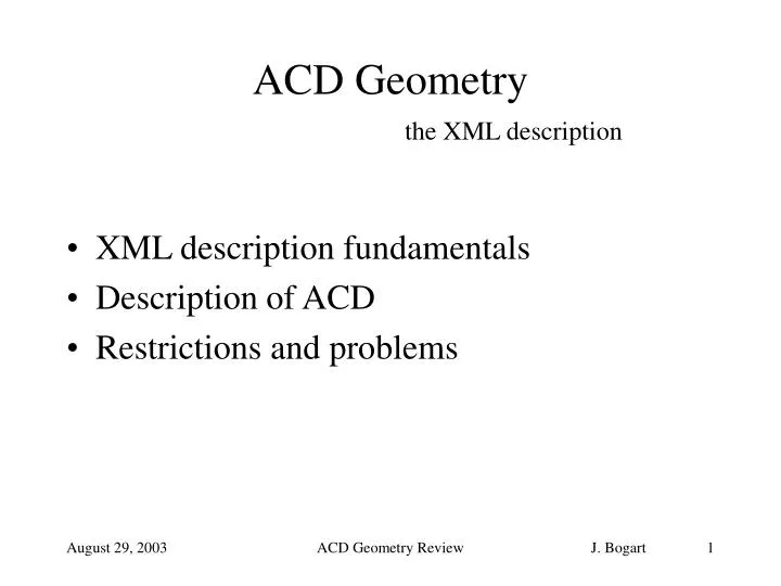
ACD Geometry the XML description • XML description fundamentals • Description of ACD • Restrictions and problems ACD Geometry Review
Geometry Document Structure • Primary constants • material names • integer constants (counts) • floating point constants (dimensions, offsets) • Derived constants (mostly offsets) • Build and nest volumes • Identifier constraints – not of interest here ACD Geometry Review
Constants To see constants and their values, go to http://www-glast.slac.stanford.edu/software/detector_description/ and click on one of the links for combined all-subsytem constants, which will bring you to a page like this one. The list is divided into categories by type (materials, integers, floating point) subsystem (TKR, CAL, ACD, NAD – Not A Detector, and global) and Primary versus Derived. ACD Geometry Review
Building the geometry • Define primitive (uniform material, simple shape) volumes • Assemble into stacks along an axis or • Position individually in a composition volume. • Compositions always have an explicit envelope volume; stacks never do. • May have arbitrary levels of nesting. • Dimensions and offsets appearing in the source volume descriptions are always referred to by name as previously-defined primary or derived constants. Literal numeric constants are never used for dimensions or offsets (occasionally used for rotations of 90 and id field values). ACD Geometry Review
Typical volumes Primitive volume (box). Has a name, material and dimensions. May also be marked as sensitive. <box name="topTileRdefCedge" XREF="topTileXEdge_l" YREF="topTileYEdge_l" ZREF="tileThickness" materialREF="tileMat" sensitive="posHit" detectorTypeREF="eDTypeACDTile" /> ACD Geometry Review
Typical volumes Stack along z-axis. Since components are immediately adjacent and are all centered in transverse dimensions, no explicit offsets are required. <stackZ name="ACDTopSupport" > <axisPos volume="ACDTopSupportFace" /> <axisPos volume="ACDTopSupportCore" /> <axisPos volume="ACDTopSupportFace" /> </stackZ> Similarly, stack along x-axis to make a volume called ACDSideSupport which is replicated 4 times in the full model. ACD Geometry Review
Typical volumes Stack along x-axis. This example also applies id fields (required for sensitive volumes) and specifies a gap between adjacent tiles. <!-- Make rows for faces (2 & 3) with lesser trans. dimension first. Side 2 rotated +90 about Z is isomorphic to side 3. --> <stackX name="sideTileRow0Face2" > <axisPos volume="sideTileR0EdgeLesser"> <idField name="fCol" value="0" /> </axisPos> <axisPos volume="sideTileR0Mid" gapREF="sideHorizontalGap" > <idField name="fCol" value="1" /> </axisPos> <axisPos volume="sideTileR0Mid" gapREF="sideHorizontalGap" > <idField name="fCol" value="2" /> </axisPos> <axisPos volume="sideTileR0Mid" gapREF="sideHorizontalGap" > <idField name="fCol" value="3" /> </axisPos> <axisPos volume="sideTileR0EdgeGreater" gapREF="sideHorizontalGap" > <idField name="fCol" value="4" /> </axisPos> </stackX> ACD Geometry Review
Typical volumes Composition of top tiles and ribbon (artificial) segments is too complicated to include fully here. Only the first two child volumes are shown. <composition name="ACDTop" envelope="ACDTopEnv"> <!-- Row 0. Has largest negative y displacement --> <posXYZ volume="topTileRdefCedge" XREF="topTileEdge_dxn" YREF="topTileEdge_dyn" ZREF="topTileEdge_dz"> <idField name="fACDCmp" valueREF="eACDTile"/> <idField name="fRow" value="0" /> <idField name="fCol" value="0" /> </posXYZ> <posXYZ volume="topTileRdefCmid" XREF="topTileMid_dxn" YREF="topTileEdge_dyn" ZREF="topTileMid_dz" > <idField name="fACDCmp" valueREF="eACDTile" /> <idField name="fRow" value="0" /> <idField name="fCol" value="1" /> </posXYZ> .... (23 more tiles go here, followed by 4 long "x-ribbon" segments and 20 little "y-ribbon" segments) </composition> ACD Geometry Review
ACD volumes All geometry description source files can be found in the package xmlGeoDbs. Several physical files can be assembled into a single XML document (which is what the application sees) by using external entities. The top file usually used for LAT geometry is xmlGeoDbs/xml/flight/flightSegVols.xml ACD volumes such as the examples on previous slides are defined in the file xmlGeoDbs/xml/flight/flightACDAcd.xml ACD Geometry Review
ACD volumes (2) • Current XML description includes • top and side supports, modeled as core with face sheets • tiles • ribbons It does not include any of the many small volumes (clips and so forth) used to hold the ribbons in place, nor does it include the substantial-looking "channels". ACD Geometry Review
Channels 'n more • 4 channels • 2 bottom side tiles • 1 side support (core) ACD Geometry Review
Simplifications • Missing volumes (see above). • Each top curved tile is modeled as a simple box of the correct x- and y-extent, thickness = 10 mm. • could improve this by adding a box in the y-z plane. Would require a more complicated scheme for tile id's and changes to software to interpret properly. • Side tiles as modeled have no slant. All side tiles for one side lie in a box aligned with axes. Thickness = tile thickness. Height has been adjusted so that there is zero gap between rows. • would be tedious but straightforward to add to xml description. Code handling rotations hasn't been exercised in quite this way to date. • Ribbons are modeled as segments (boxes) which are always aligned with the axes. Since side tiles have been simplified, only need one segment for each ribbon along each side. • Ribbons are not sensitive • easy to modify xml to make them sensitive. ACD Geometry Review
Curved tile ACD Geometry Review
Curved tiles & vicinity The gap in x (3-d model or simulated) from curved top tile to nearest side is about 4 mm. In simulation the top tile extends in x and y to fill the yellow bounding box but has constant thickness of 10 mm (same as real tile, excluding curved portion). Proposed enhancement, if needed, would be to add a vertically-oriented box for each curved tile which would extend down 50 mm from the main horizontal piece; that is, as far as the actual curved tile does. ACD Geometry Review
Slanted side tiles Tiles from the +Y side, projected along x-axis. XML description aligns them all along standard axes, adjusting lengths so they just fit with no gaps. ACD Geometry Review
Ribbons ACD Geometry Review