Download
1 / 21
210 likes | 486 Views
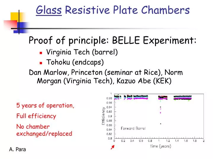
Glass Resistive Plate Chambers. Proof of principle: BELLE Experiment: Virginia Tech (barrel) Tohoku (endcaps) Dan Marlow, Princeton (seminar at Rice), Norm Morgan (Virginia Tech), Kazuo Abe (KEK). 5 years of operation, Full efficiency No chamber exchanged/replaced. A. Para.

E N D
Glass Resistive Plate Chambers Proof of principle: BELLE Experiment: • Virginia Tech (barrel) • Tohoku (endcaps) Dan Marlow, Princeton (seminar at Rice), Norm Morgan (Virginia Tech), Kazuo Abe (KEK) 5 years of operation, Full efficiency No chamber exchanged/replaced A. Para
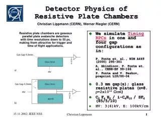
RPC Principles of Operation Resistive paint Signal pickup (x) Glass plates 8 kV Signal pickup (y) Resistive paint +++++++++++++++ _ _ _ _ _ _ _ _ _ _ _ +++ +++++ _ _ _ _ _ _ _ Spacers A passing charged particle induces an avalanche, which develops into a spark. The discharge is quenched when all of the locally ( ) available charge is consumed. Before The discharged area recharges slowly through the high-resistivity glass plates. After
Plateau Curve 2 mm gap RPCs plateau at a fairly high voltage. Note the slight falloff in efficiency well above the plateau. This effect is real and typical.
BELLE chamber design Two float glass sheets, 2 mm thick Noryl spacers Epoxy 3M 2216 India ink (30%black + 70%white) Gas connectors Very simple device
Gas Mixture (Belle) • Traditional Gas Mixture • 64% Argon : 6% Freon 116 30% Isobutane • Constraints • Safety: gas should be non flammable: • mixture ---> 30% Argon : 62% Freon :8% Butane • Environment: Freon 116--> Freon R134A • Cost: Isobutane ---> Butane “silver” • Streamer mode operation: large, robust signals 100-200 pC
First result: signal from streamer mode Repond, Lia, (Argonne) • Gas: Freon/Argon/IsoButane at 62:30:8 • High Voltage: 7.5 KV or above • Cosmic ray signal (triggered by 3 layers of scintillator) PED + avalanche PED 1 streamer 2 streamers 3 streamers avalanche
Production cost, materials RPC Material per m2 Glass @ $0.40/lb $10 Mylar (5mil) $3 Spacers $5 Conductive paint $1.50 Epoxy $4 Gas fittings (injection molded) $2 Misc. supplies $2 Total $27.50/m2
RPC production, Virginia model Gllass is placed on a conveyor that moves the glass or RPC through an automatic wash/rinse/dry cycle ready for epoxy or painting. Clean glass is diverted to a gluing station where the spacers and edges are epoxied to the glass plate. Virginia Tech experience indicates that it will take 15-30 mins to glue the spacers. We will use 30 mins for the estimate. The second sheet is flipped lowered onto the first epoxied sheet. Epoxied RPCs are moved to a curing station. There are two curing stations. Freshly glued chambers are stacked on one. Cured RPCs from the previous day’s stack are moved to a leak-check station. Chambers which fail the leak test are discarded (much less that 1% from Virginia Tech experience) Top surface of the chamber is cleaned and painted with Statguard Conductive Acrylic Paint (DESCO 10408) After inking the RPC is either flipped and sent back to the cleaning input line for the other side or passed to a station for HV connection application and packing
RPC production shift personnel • Material movers – moving/opening crates and feeding glass into the assembly line and loading modules for shipment. 2 • line worker - monitoring cleaning process 1 • line workers - laying down spacers and lowering top sheet of glass 3 • line worker - monitoring inking and drying 1 • line worker – monitoring leak check and curing process and resupplying the assembly line 1 • foreman – supervisor, quality control, procurement 1 Total per shift 9
Expected yield • 1 chamber is produced every 30 mins, 16 chambers per 8 hours shift. • 2 shifts per day, 220 days per year. • 440 shifts per year give production capability of 7040 chambers per facility per year. • Two factories will produce 48,000 chambers in 3.5 years
Factory cost • Assembly line equipment $400K • Floor space 5000 ft2 @ $16.25/ft2/yr $85K/year • Labor $1000K/year Labor breakdown: • 16 technicians @ $50k/year $800K/year • 2 foremen @ $60k/year $120K/year • 1 project manager $80K/year
RPC Assembly at Va Tech To reduce assembly time, extruded strips were used instead of “button-like” spacers. This also provided a natural “mouse maze” to ensure uniform distribution of the gas. This is the slowest step in the production
Improving the BELLE design • Cut the corner, make the gas manifold: improve coverage/reduce dead area, improve robustness of a chamber • Replace India ink by Static quard conductive acrylic paint : Do not depend on unspecified properties of the proprietory products • replace 2mm glass by 3 mm glass: Reduce breakage, improve robustness • Replace epoxy by transfer tape for gluing spacers: Enable full automation of the production process • Reduce number of spacers, 20 cm pitch instead of 10: Take advantage of thicker glass, simplify the production.
Gaining experience/confidence with RPC’s • Gas leaks. How big are they? Examine large area chambers from Virginia: • Few have broken connectors • One leaks 30 ccm/min • Two leak 3-5 ccm/min • For the rest the leak rate is below the threshold of detectability • Leaks? Do they matter? • Does a leaky chamber work? • How poorly?
Efficiency of a chamber with the biggest leak • Despite a sizeable leak, the chamber shows a pretty good efficiency, ~ 90% • But this efficiency seems do degrade with time ?
Efficiency of a chamber with the biggest leak • But this efficiency seems do degrade with time ? • This chamber was operated with no gas flow • Indication that the gas composition/contamination is not very important ?
Building small chambers Some 20 chambers constructed this summer by a TRAC teacher Efficiency in excess of 95% Constructed a setup for long term studies of a large collection of chambers
Further ideas to test ? • Glass with embedded resistive layer? • Simplify the production ( no washing, painting of one side) • Laminate with an insulating plastic? • Simplify the process • Improve the safety of the production process
Conclusions • Experience, so far, is very positive: confirming the BELLE conclusion, albeit on a very much smaller scale, that glass RPC’s are very robust detectors suitable for large detectors • A systematic studies of the glass RPC has commenced, but it will be a long time before we can add much to the BELLE experience • Production of chambers lends itself to the automation, thus offering a significant potential for further cost reductions • Commercial: today, 5 pm, LabF: show and tell. See for yourself small chambers and large chambers, production process, cosmic rays test stand.