Download
1 / 30
330 likes | 427 Views
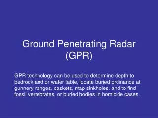
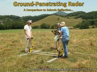
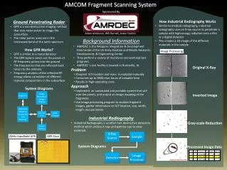
Medium Frequency Ground Penetrating Radar (GPR). Ground Penetrating Radar (also known as Ground Probing Radar / Georadar ) is a noninvasive geophysical technique for subsurface exploration. Authors: B. Divya Priya , M.Tech (Remote Sensing)

E N D
Medium Frequency Ground Penetrating Radar (GPR) Ground Penetrating Radar (also known as Ground Probing Radar / Georadar) is a noninvasive geophysical technique for subsurface exploration. Authors: B. DivyaPriya, M.Tech (Remote Sensing) Department of Civil Engineering Indian Institute of Technology Bombay
Learning Objectives: After interacting with this Learning Object, the user will be able to: • explain the principle of GPR • identify which frequency is suitable for detection of objects beneath the ground surface • identify the location of the object based on the profile obtained in the radargram.
Definitions: a) Antenna- It is the transducer consisting of both Transmitter and Receiver for transmission and reception of electromagnetic waves. b) Data Logger/Viewer- It is an electronic device that records the data in relation to time or location and also display it using monitor. c) Radargram- The picture of the subsurface profile (graph like) representing a profile length along x-axis and y-axis representing the depth range is called Radargram. The radargrams constitute the raw Ground Penetrating Radar data.
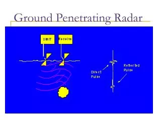
Concept: • GPR sends electromagnetic energy into the ground through a Transmitter Antenna, and the transmitted energy gets reflected wherever there is a Dielectric Contrast between the subsurface layers. • The reflected energy is collected by Receiver antenna and is displayed in real time on the screen of the Data-Logger. • Monostatic and Bistatic antennae : If the Transmitter and Receiver are housed in a single transducer, it is Monostatic. Otherwise, it is Bistatic. The illustrations in this learning object are Bistatic.
Concept: Dielectric constant (ξr ): It is the capacity of a material to store a charge when an electric field is applied to it. ξr = (c/v)2 …………… equation (1) ξr = (ct/D)2 …………… equation (2) where: ξr = Dielectric constant c = speed of light (30 cm/nanosecond) v = velocity of electromagnetic energy passing through the material. D = depth of penetration t = two way travel time of the pulse.
Facts : Table 1: Dielectric Constants Of Some Common Materials
Facts: Table 2: Applications of GPR
Diagram - Processing of GPR Data: Processing of GPR Data Distance normalization ,Horizontal Scaling (stacking) , Vertical frequency Filtering [high- and low-pass filters], Horizontal filtering , Velocity corrections Deconvolution, Background removal, Spatial FFT, Migration Gain correction Pre Processing Post Processing Improve the quality of the data Correct the data Setting the range i.e. two way travel time of the pulse Setting the dielectric constant of the material or surface to be explored choose low and high pass filters to define the range around the central frequency within which the data is to be collected Techniques used
Concept: Interpretation of GPR Data • One of the most important applications is identification of buried cylindrical objects like pipes and conduits. This is based on the appearance of a convex hyperbola in the data. For this, the technique of Migration is applied to the GPR data to fit a theoretical hyperbola, which best matches the observed one and thereby obtain the depth and diameter of the object. • In other situations visual interpretation of the post processed data may help. Alternatively, digital classification of the radargram data using techniques such ANN or Support Vector Machines may be used.
Analogy / Scenario / Action 1 GPR moves at a constant speed over the ground. Transmitter sends a pulse into the ground. Reflection from buried objects or contacts between subsurface layers are picked up by Receiver. As GPR moves over the surface the data logger displays amplitudes of reflected signals as a distance v/s depth plot (radargram) in real time. 2 3 4 5
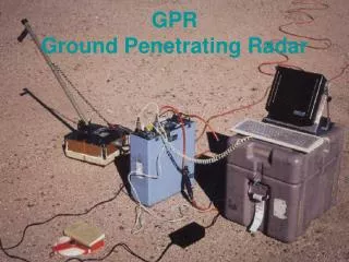
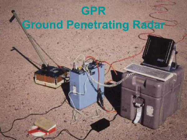
Diagram for reference Data logger Trolley Antenna
Link for the animator • http://www.sandberg.co.uk/ground-radar/gpr-principles.htm The man moves continuously (but slowly) from start to end – master layout
Master Layout 1 1 Profile Length 2 Depth Silty sand 3 Sand stone Limestone Marine ss Radargram Coal 4 Clay Limestone Pipe Shale 5
Step 1:When the GPR is at the start of the survey 1 Refer to master layout 1 2 3 4 5
Master Layout 2 1 Profile Length Depth 2 Silty sand 3 Sand stone Marine ss Limestone 4 Clay Indication of Pipe in Radargram as hyperbola Limestone Pipe Shale 5
Step 2:When the GPR is exactly above the pipe 1 Refer to master layout 2 2 3 4 5
Master Layout 3 1 Profile Length Depth 2 Silty sand 3 Sand stone Marine ss Limestone 4 Clay Limestone Pipe Shale 5
Step 2:When the GPR is at the end 1 Refer to master layout 3 2 3 4 5
Credits What will you learn Radio buttons (if any)/Drop down (if any) Play/pause Restart Lets Learn! Interactivity options Sliders(IO1) / Input Boxes(IO2) /Drop down(IO3) (if any) Definitions Concepts Diagram Animation Area Facts Test your understanding (questionnaire) Lets Sum up (summary) Want to know more… (Further Reading) Output result of interactivity (if any) Instructions/ Working area
The man will move the GPR as shown from master layout 1 – 2 – 3 Radargram (appears left to right) 0.5 m 1 m Silty sand Sand stone 4 m Limestone Choose frequency Marine ss 6 m 100 MHz 7 m 200 MHz Clay 270 MHz Limestone Pipe 400 MHz 900 MHz Shale 1600 MHz 20 m
1 2 If user selects 270/200/100 then display this radargram If user selects 1600/900/400 then display this radargram 3 Hyperbola 4 5
Interactivity option1 :Step No1 1 Refer to slide 20 and 21 2 3 4 5
The man will move the GPR as shown from master layout 1 – 2 – 3 Radargram (appears left to right) 0.5 m 1 m Silty sand Sand stone 4 m Limestone Marine ss 6 m 7 m Clay Limestone Pipe Shale 20 m
Example 1 Example 2 0.5 m 0.5 m 0.5 m 0.5 m 1 m 1 m 1 m 1 m The hyperbola should be shown exactly at the position where user places the pipe Silty sand Silty sand Sand stone Sand stone 4 m 4 m 4 m 4 m Marine ss Marine ss 6 m 6 m 6 m 6 m 7 m 7 m 7 m 7 m Limestone Limestone Clay Clay Limestone Limestone Pipe Pipe Shale Shale 20 m 20 m 20 m 20 m
Interactivity option2 :Step No1 1 Refer to slide 23 2 3 4 5
Questionnaire 1 1. What is radargram? a) The chart between length of the profile and the frequency b) The graph with Profile length as X- axis and frequency as Y- axis c) The signal showing variation in amplitude along length d)The graph with profile length as X-axis and depth of penetration as Y-axis. 2. How does the depth of penetration of transmitted pulse vary as frequency increases? a) Increases b) decreases c) does not change d) initially increases and remains constant beyond a certain frequency 2 3 4 5
Questionnaire (contd..) 1 3. What kind of reflection is seen typically in the radargram when GPR crosses a pipe? a) Hyperbolic b) Circular c) elliptical d) cylindrical 4. How does the depth of penetration of transmitted pulse vary as dielectric constant increases? a) Increases b) decreases c) does not change d) initially increases and remains constant beyond a certain frequency 5. Which frequency antenna is suitable for Concrete Evaluation? a) 200MHz b) 1270MHz c) 1600MHz d) 400MHz 2 3 4 5
Summary: • Ground Penetrating Radar (also known as Ground Probing Radar / Georadar) is a noninvasive geophysical technique for subsurface exploration. • GPR sends electromagnetic energy into the ground through a Transmitter Antenna, and the transmitted energy gets reflected wherever there is a Dielectric Contrast between the subsurface layers. The reflected energy is collected by Receiver antenna and is displayed in real time on the screen of the Data-Logger. • GPRs are designed to operate in specific central frequencies ranging from 15MHz to 2GHz
Links for further reading: Reference websites: 1) http://www.geophysical.com/ 2) http://en.wikipedia.org/wiki/GPR 3) http://www.g-p-r.com/ Books: Jol, Harry. M., (2009), “Ground Penetrating Radar : Theory and Applications”, 1st Ed., Elsevier Science.
Links for further reading contd.. Research papers: Yelf. R.J. (2007). Application of Ground Penetrating Radar to Civil and Geotechnical Engineering. Electromagnetic Phenomena, Vol- 7,No-18 Sato, M. (2001). Fundamentals of GPR data interpretation.Toholur University, Japan. Davis, J.A. (1989). Ground-penetrating radar for high-resolution mapping of soil and rock stratigraphy, Geophysical Prospecting, 37 , 531 - 551.