Download
1 / 27
400 likes | 1.62k Views
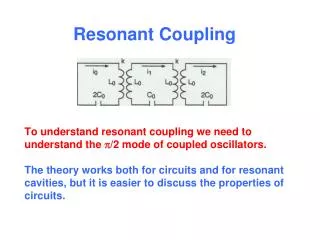
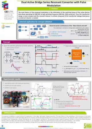
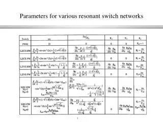
Series Resonant Inverter with Bidirectional Switch. Turn Q 1 ON at t = 0 A “resonant” pulse of current flows, charging C to V C1 , Q1 turns OFF. C charges to V C1 , Q1 turns OFF. C discharges via D1 and V s. For t > t 1 The capacitor acts as a voltage source

E N D
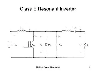
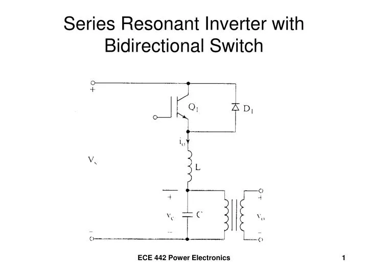
Series Resonant Inverter with Bidirectional Switch ECE 442 Power Electronics
Turn Q1 ON at t = 0 A “resonant” pulse of current flows, charging C to VC1, Q1 turns OFF ECE 442 Power Electronics
C charges to VC1, Q1 turns OFF ECE 442 Power Electronics
C discharges via D1 and Vs • For t > t1 • The capacitor acts as a voltage source • Current io reverses, and flows via D1 to VS ECE 442 Power Electronics
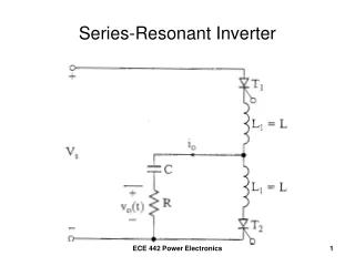
“Idealized Version” ECE 442 Power Electronics
Half-Bridge Series Resonant Inverter ECE 442 Power Electronics
Turn Q1 ON, Resonant Pulse of current appears. ECE 442 Power Electronics
Turn Q2 ON, Resonant Pulse of current appears in the opposite direction, and goes to zero. ECE 442 Power Electronics
Waveform Summary ECE 442 Power Electronics
Overlapping and Non-Overlapping modes • Non-Overlapping Mode • Firing of the switching device is delayed until the last current oscillation through the diode is completed ECE 442 Power Electronics
Overlapping and Non-Overlapping modes • Overlapping Mode • Firing of the switching device occurs before the last current oscillation through the diode is completed. • This increases the output frequency and the output power ECE 442 Power Electronics
MultiSim Simulation ECE 442 Power Electronics
Non-Overlapping Mode ECE 442 Power Electronics
Overlapping Mode ECE 442 Power Electronics
Full-Bridge Series Resonant Inverter ECE 442 Power Electronics
Frequency Response of Series-Resonant Inverters ECE 442 Power Electronics
Series-Loaded Inverter • Load Resistor in series with L and C ECE 442 Power Electronics
Frequency Response ECE 442 Power Electronics
Parallel-Loaded Case ECE 442 Power Electronics
Frequency Response ECE 442 Power Electronics
Series-Parallel Loaded Case ECE 442 Power Electronics
Frequency Response ECE 442 Power Electronics