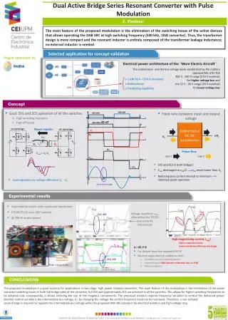
Download
1 / 34
380 likes | 616 Views
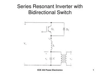
Series-Resonant Inverter. Operation. T 1 fired, resonant pulse of current flows through the load. The current falls to zero at t = t 1m and T 1 is “self – commutated”. T 2 fired, reverse resonant current flows through the load and T 2 is also “self-commutated”.

E N D
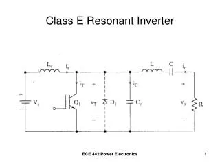
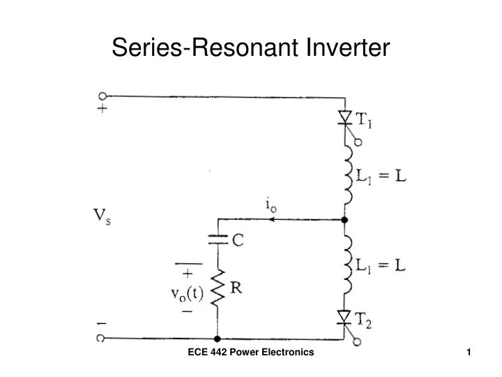
Series-Resonant Inverter ECE 442 Power Electronics
Operation T1 fired, resonant pulse of current flows through the load. The current falls to zero at t = t1m and T1 is “self – commutated”. T2 fired, reverse resonant current flows through the load and T2 is also “self-commutated”. The series resonant circuit must be underdamped, R2 < (4L/C) ECE 442 Power Electronics
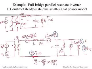
Operation in Mode 1 – Fire T1 ECE 442 Power Electronics
To find the time when the current is maximum, set the first derivative = 0 ECE 442 Power Electronics
To find the capacitor voltage, integrate the current The current i1 becomes = 0 @ t=t1m ECE 442 Power Electronics
Operation in Mode 2 – T1, T2 Both OFF ECE 442 Power Electronics
t2m ECE 442 Power Electronics
Operation in Mode 3 – Fire T2 ECE 442 Power Electronics
Summary -- Series Resonant Inverter ECE 442 Power Electronics
To avoid a short-circuit across the main dc supply, T1 must be turned OFF before T2 is turned ON, resulting in a “dead zone”. This “off-time” must be longer than the turn-off time of the thyristors, tq. The maximum possible output frequency is ECE 442 Power Electronics
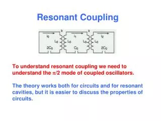
Series Resonant Inverter Coupled Inductors ECE 442 Power Electronics
Improvement in performance • When T1 turned ON, voltage @ L1 is as shown, voltage @ L2 in same direction, adding to the voltage @ C • This turns T2 OFF before the load current falls to 0. ECE 442 Power Electronics
Half-Bridge Series Resonant Inverter Note: L1 = L2 C1 = C2 ECE 442 Power Electronics
This configuration reduces the high-pulsed current from the dc supply • Power drawn from the source during both half-cycles of the output. • Half of the current is supplied from the associated capacitor, half of the current is supplied from the source. ECE 442 Power Electronics
Full-Bridge Series-Resonant Inverter ECE 442 Power Electronics
Characteristics of the full-bridge inverter • This configuration provides higher output power. • Either T1-T2 or T3-T4 are fired. • Supply current is continuous but pulsating. ECE 442 Power Electronics
Example 8.1 – Analysis of the Basic Resonant Inverter • L1 = L2 = L = 50μH • C = 6μF • R = 2Ω • Vs = 220V • fo = 7kHz • tq = 10μs ECE 442 Power Electronics
Determine the resonant frequency The resonant frequency in Hz ECE 442 Power Electronics
Determine the turn-off time toff ECE 442 Power Electronics
Determine the maximum permissible frequency ECE 442 Power Electronics
Determine the peak-to-peak capacitor voltage ECE 442 Power Electronics
Determine the peak load current ECE 442 Power Electronics
Sketch the instantaneous load current, capacitor voltage, and dc supply current ECE 442 Power Electronics
Calculate the rms load current ECE 442 Power Electronics
Using MATHCAD, Io = 44.1Amperes ECE 442 Power Electronics
Determine the output power ECE 442 Power Electronics
Determine the average supply current ECE 442 Power Electronics
Determine the average, peak, and rms thyristor currents ECE 442 Power Electronics
rms Thyristor Current Using MATHCAD ECE 442 Power Electronics