Download
1 / 92
940 likes | 966 Views
MIPS Pipelining: Part I. Textbook and References. Textbook(s): Computer Architecture: A Quantitative Approach 4 th Edition, David A. Patterson and John L. Hennessy, Morgan Kaufmann Publishers, 2005. (ISBN: 0-12-370490-1)

E N D
MIPS Pipelining:Part I Dr. Anilkumar K.G
Textbook and References Textbook(s): • Computer Architecture: A Quantitative Approach 4th Edition, David A. Patterson and John L. Hennessy, Morgan Kaufmann Publishers, 2005. (ISBN: 0-12-370490-1) • Digital Design and Computer Architecture, 2nd Edition, David M.H and Sarah L.H, Morgan Kaufmann, Elsevier, 2013 (ISBN: 978-0-12-394424-5) Reference(s): • Computer Architecture and Implementation, Harvey G. Cragon, Cambridge University Press, 2000 (ISBN: 0-52-165168-9) Simulator: Tasm (Turbo Assembler) Link: https://en.wikipedia.org/wiki/MIPS_instruction_set Dr. Anilkumar K.G
Objective(s) • One of the objectives of this study is to make each student to familiar with the pipeline architecture of a commercial Microprocessor such as MIPS system. • Once the students gain the knowledge of the pipelined hardware structure of a microprocessor, then it is possible for them to apply that into any microprocessor related fields. • Finally, the students will get the knowledge of the complete operation a computer system. Dr. Anilkumar K.G
Introduction • This section describes the features of a five-stage RISC(Reduced Instruction Set Computer) pipeline machine – MIPS 32-bit system and its issue of hazards and performance problems. Dr. Anilkumar K.G
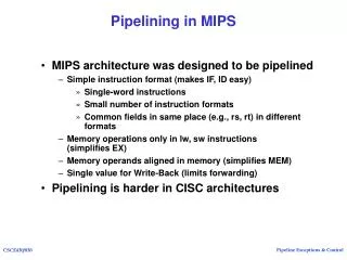
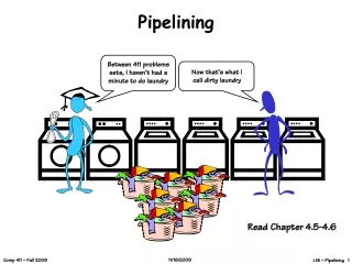
What is Pipelining? • Pipeline is a performance improvement technique- multiple instructions are overlapped in execution • Pipeline takes advantages of parallelism that exists among the actions needed to execute an instruction • Today, pipelining is the key performance techniqueused to make fast CPUs • A pipeline is like an automobile assembly line • In a computer pipeline, each step in the pipeline completes a part of an instruction, each of these steps called a pipe stage or a pipe segment • The stages are connected one to the next to form a pipe Dr. Anilkumar K.G
Pipelining • In an automobile assembly line, throughput is defined as the no. of vehicles per hour • The throughputof an instruction pipeline is determined by how often an instruction exits in the pipeline • Because the pipeline stages are hooked together, all the stages must be ready to proceed at the same time • The time required between moving an instruction from one stage to the next of the pipeline is a processor cycle (or a pipeline cycle) • Length of a processor cycle is determined by the time required for the slowest pipe stage Dr. Anilkumar K.G
Pipelining Dr. Anilkumar K.G
Goal of Pipelining Designer • Goal of a pipeline designer is to balance the length of each pipeline stages • If the stages are perfectly balanced, then the time per instruction on the pipelined processor is Time per instruction on unpipelined machine Number of pipeline stages in a pipelined machine • The speedup from pipelining equals to the no. of pipe stages (only when the pipeline CPI is 1) Dr. Anilkumar K.G
Goal of Pipelining Designer • Pipelining yields a reduction in the average execution time per instruction • Pipelining does not reduce the execution time of an instruction • The reduction can be viewed as decreasing • CPI, • Clock cycle time, • Or combination of both • Pipelining is an implementation technique that exploits parallelism among the instructions in a sequential instruction stream • It is not visible to the programmer Dr. Anilkumar K.G
The Basic MIPS Instruction Set • MIPS architectures are characterized by the following few key properties: • All operations on data apply to data in registers and typically change the entire register (32 bits/reg in a MIPS-32bit system) • The only operations that affect memory are load and storeoperations • Load and store operations that load or store a full register • Size of an instruction is fixed • These properties simplifies the implementation of pipeliningin RISC processors (MIPS is a RISC processor) Dr. Anilkumar K.G
Five Stages of MIPS Pipeline Unit • IF(Instruction fetch) stage: • Send the PC (Program Counter) to memory and fetch the current instruction from memory • Update the PC for the next sequential instruction by adding 4 to the PC (each instruction is 4byte in size) • ID (Instruction decode/register fetch): • Decode the instruction and read the operand registers from the register file • Do the equality test on the registers, for branch test • Compute the branch target address by adding the offset to the incremented PC Dr. Anilkumar K.G
A simple Implementation of a RISC Instruction Set • Instruction decoding done in parallel with reading registers, because register specifiers are at a fixed location in a RISC architecture, called fixed-field decoding • EX (Execution/effective address cycle): • Memory reference operation: ALU adds the base register and the offset to form the effective address for load/store • Register-Register operation: ALU performs the operation specified by the ALU opcode on the value given by register operands • Register-Immediate operation: ALU performs the operation specified by the ALU opcode based on the immediate value Dr. Anilkumar K.G
A simple Implementation of a RISC Instruction Set • MEM (Memory access) stage: • If the operation is a load, memory read uses the effective address which is computed in the previous cycle • If it is a store, the memory writes happen using the effective address • WB (Write-back result to register file) stage: • WB stage is supports only reg-reg and load instructions • Write the result into the register file, whether is from memory (load) or from ALU Dr. Anilkumar K.G
Classic Five-stage Pipeline for a RISC Processor • Each of the clock cycle from previous section becomes a pipe stage – a cycle in the pipeline • Pipe stages shown in Figure A.1 • Although each instruction takes 5 clock cycles to complete (each stage needs 1 cock cycle), during each clock cycle the HW will initiate new instruction Dr. Anilkumar K.G
Classic Five-stage Pipeline for RISC Processor Dr. Anilkumar K.G
Classic Five-stage Pipeline for RISC Processor • In a pipeline, we don’t try to perform two different operations with the same data path resource on the same clock cycle • A single ALU cannot be asked to compute an effective address and perform a subtract operation at the same time • we must ensure that the overlap of instructions in the pipeline cannot cause such a conflict • Figure A.2 shows a simplified version of a RISC data path drawn in pipeline fashion Dr. Anilkumar K.G
Classic Five-stage Pipeline for RISC Processor • Figure A.2 showed that the major functional units are used in different cycles, and hence overlapping the execution of multiple instructions causes a few conflicts • There are threeobservations: • First- The use of separate instruction and data caches eliminates a conflict (resource conflict) for a single memory for instruction and data accesses • Second- The register file is used in the two stages: one for reading in ID stage and one for in WB stage • Need to perform two reads and one write every clock cycle • To handle reads and a write to the same register, perform write in the first half and the read in the second half of the clock cycle Dr. Anilkumar K.G
Classic Five-stage Pipeline for RISC Processor • Third – To start a new instruction every clock cycle, increment and store PC every clock in the IF stage • Must keep an adder in the ID stage to compute the potential branch target • Must insure that instructions in different stages of the pipeline do not interfere with one another- HW resource conflict • Hence each stage of the pipeline is separated by introducing pipeline registers(Figure A.3) • So that at the end of a clock cycle all the results from a given stage are stored into a register (buffer) that is used as the input to the next stage on the next cycle Dr. Anilkumar K.G
Classic Five-stage Pipeline for RISC Processor • The pipeline registers play the key role of carrying intermediate results from one stage to another where the source and destination may not be directly adjacent • For ex. the register value to be stored during a store instruction is read during ID, but not actually used until MEM; • It is passed through two pipeline registers to reach the data memory during the MEM stage • Likewise, the result of an ALU instruction is computed during EX, but not actually stored until WB; it arrives there by passing through two pipeline registers • Look at the details of a four-stage pipeline to get a clear pipeline idea! Dr. Anilkumar K.G
Basic Performance Issue in Pipelining • Pipelining increases CPU’s instruction throughput • The no. of instructions completed per unit time increases • Pipeline does not reduce the execution time of an individual instruction • But it increases the exe. time of each instruction due to overhead in the control of the pipeline mechanism • Due to pipeline process, a program runs faster even though no single instruction runs faster • Issues arise from pipeline are latency, imbalance among pipeline stages and pipeline overhead Dr. Anilkumar K.G
Basic Performance Issue in Pipelining • Imbalance among the pipe stages reduces performance since the clock cannot run faster than the time needed for the slowest stage (such as memory access) • Pipeline overhead arises from the combination of pipeline register delay and clock skew • That is, pipeline registers add setup time and propagation delay to the system • Clock skew is the maximum delay between when the clock arrives at any two pipeline registers • In a Pipeline, average instr. execution time can be given as: Average instruction exe. time = Clock cycle time x Average CPI Dr. Anilkumar K.G
Example Dr. Anilkumar K.G
The Major Hurdle of Pipelining – Pipeline Hazards • In a pipeline, there situations called hazards, that prevent the next instruction in the instruction- stream from executing during its designated clock cycle • Hazards reduce performance from pipelining Dr. Anilkumar K.G
Classes of Pipeline Hazards • There are classes of hazards: • Structural hazards arise from resource conflicts when the HW cannot support all possible combinations of instructions simultaneously in overlapped execution (pipelined execution) • Data hazards arise when an instruction depends on the results of a pervious instruction in a way that is exposed by the overlapping of instructions in the pipeline • Control hazards arise from the pipelining of branch instructions and other instructions that change the PC • Hazards in pipelines can make it to stall the pipeline Dr. Anilkumar K.G
Performance of Pipelines with Stalls • A stall (delay) causes the pipeline performance to degrade from its ideal performance Speedup from pipelining =Avg. instruction exe.timeunpipelined Avg. instruction exe.timepipelined = CPIunpipelined x clockcycleunpipelined CPIpipelined x clockcyclepipelined = CPIunpipelined x clockcycleunpipelined CPIpipelined clockcyclepipelined • The ideal CPI on a pipelined processor is always 1 CPIpipelined = CPIideal + Pipeline stall clock cycles/instruction = 1 + Pipeline stall clock cycles/instruction (delay)(2) (1) Dr. Anilkumar K.G
Performance of Pipelines with Stalls • If we ignore the cycle time overhead and assume the stages are perfectly balanced, then the clock cycle time of pipelined and un-pipelined processors are equal, hence speedup; Speedup = CPIunpipelined 1 + Pipeline stall cycles/instruction (3) • A case where all instructions take the same no. of cycles, which must also be equal to the no. of pipeline stages, called the pipeline depth • In this case, the CPIunpipelined is equal to the depth of the pipeline (Pipelinedepth), hance Speedup = Pipelinedepth 1 + Pipeline stall cycles/instruction(4) Dr. Anilkumar K.G
Structural Hazards • When a processor is pipelined, the overlapped execution of instructions requires pipelining of its functional units (stages) • If some combination of instructions cannot be pipelined properly due to resource conflicts, the processor is said to have a structural hazard • That is, structural hazards arise when some functional unit is not fully pipelined • Hence a sequence of instructions using that HW resource cannot proceed at the rate of one per clock cycle • some HW resource has not been duplicated enough to allow all combinations of instructions in the pipeline can also cause structural hazards • For ex. a processor have only one register-file write port, the pipeline wants to perform two write in a clock cycle generates a structural hazard Dr. Anilkumar K.G
Structural Hazards • When a structural hazardencounters, the pipeline will stall one of the instructions until the required resource is available • Such stalls will increase the pipeline CPI • Figure A.4 shows a processor structural hazard with one memory port for instruction and data • To resolve this hazard, we need to stall the pipeline for 1 clock cycle when data memory access occurs • A stall in a pipeline is called pipeline bubble or bubble • Figure A.5 shows a pipeline stalled for a structural hazard – a load instruction with one memory port • After stall, simply shifting instruction 3 to the right Dr. Anilkumar K.G
Structural Hazards • A pipelined processor without the structural hazard will run faster • Designer should provide a separate memory access for instructions either by splitting cache into instruction and data caches or by using instruction buffers to hold instructions Dr. Anilkumar K.G
Data Hazards • A major effect of pipelining is to change the relative timing of instructions by overlapping their execution • This overlap introduces data and control hazards • Data hazards occur when the pipeline changes the order of read/write accesses to operands • So that the order differs from the order seen by sequentially executing instructions on an unpipelined processor • Consider the pipelined execution of below instructions DADD R1, R2, R3 DSUB R4, R1, R5 AND R6, R1, R7 OR R8, R1, R9 XOR R10, R1, R11 All instructions after DADD use the result of DADD instruction. DADD writes R1 in the WB stage, but DSUB reads the valueduring its ID stage. This problem is called a data hazard(Figure A.6). DSUB will read the wrong value and try to use it. Dr. Anilkumar K.G
Data Hazards • The AND instructions also affected by the hazard, the write of R1 does not complete until the end of clock cycle 5 • Thus AND instruction reads registers (R1 and R7) during clock cycle 4 will receive wrong results • The XOR instruction operates properly because its register read occurs in clock cycle 6, after the register write • The OR instruction also operates without incurring a hazard because register reads perform thesecond half of the cycle and writes perform in the first half of the cycle Dr. Anilkumar K.G
Minimizing Data Hazard Stalls by Forwarding • The problem caused by data hazard (Figure A.6) can be solved with a simple HW technique called forwarding (also called bypassing) • The key insight of forwarding is that the result is not really needed by the DSUB until after the DADD actually produces it • If the result can be moved from the pipeline register where DADD stores it to the DSUB, then a stall can be avoided • Forwarding works as follows: • The ALU result from both the EX/MEM pipeline registers is always fed back to the ALU input • If the forwarding HW detects the previous ALU operation has written result into the pipeline register, control logic selects that from the pipeline register rather than reading from register file Dr. Anilkumar K.G
Minimizing Data Hazard Stalls by Forwarding • Figure A.6 shows, we need to forward results not only from the immediate previous instruction but from an instruction that started 2 cycles earlier • Figure A.7 shows example with the bypass paths • Forwarding can be generalized to include passing a result directly to the functional unit that requires it • A result is forwarded from the pipeline register to the input of the another needed unit Dr. Anilkumar K.G
Minimizing Data Hazard Stalls by Forwarding • Consider the following sequence: DADD R1, R2, R3 LD R4, 0(R1) SD R4, 12(R1) • To prevent a stall in this sequence, we need to forward the values of the ALU output and memory unit output from the pipeline registers to the ALU and data memory inputs • Figure A.8 shows the forwarding path for this sequence Dr. Anilkumar K.G
Data Hazards Requiring Stalls • Not all potential data hazards can be handled by forwarding • Consider the following instruction sequence: LD R1, 0(R2) DSUB R4, R1, R5 AND R6, R1, R7 OR R8, R1, R9 • The pipeline data path with the bypass paths for this instruction sequence is shown in Figure A.9 • The LD instruction does not have the data until the end of the clock cycle 4 (MEM cycle), while the DSUB instruction needs data by the beginning of that clock cycle – this data hazard caused by LD instruction cannot be eliminated with simple HW Dr. Anilkumar K.G
Data Hazards Requiring Stalls • As Figure A.9, a forwarding path would have to operate backward in time • A capability not yet reached computer designers! • It can be possible to forward the result immediately to the ALU from the pipeline registers for use in AND instruction, which begins 2 clock cycles after the load • Likewise, OR instruction has no problem with hazard • For the DSUB instruction, the forwarded result arrives too late! • Hence needs to stall the pipeline Dr. Anilkumar K.G
Pipeline Interlock • The LD instruction has a delay (latency) that cannot be eliminated by forwarding alone • An additional HW, called a pipeline interlock needed here to preserve the correct execution pattern • The pipeline interlockdetects a hazard and stalls the pipeline until the hazard is cleared • In this case the interlock stalls the pipeline until the source instruction produces needed data • The pipeline interlock introduces a stall or bubble, just as it in the structural hazard • The CPI for the stalled instruction increases by the length of the stall (Figure A.10) Dr. Anilkumar K.G
Pipeline Interlock • Figure A.10 shows the pipeline before and after stall • Because the stall causes the instructions starting with the DSUB to move 1 cycle later in time • The forwarding to the AND instruction goes through register file and no forwarding at all is needed for the OR instruction • The insertion of bubble causes the no. of cycles to complete this instruction sequence to grow by one • No instruction is started during the clock cycle 4 and none finishes during cycle 6 Dr. Anilkumar K.G
Pipeline Interlock Time (clock cycles) 1 2 3 4 5 6 7 I n s t r. O r d e r ldr1, 0(r2) dsub r4,r1,r6 and r6,r1,r7 or r8,r1,r9 Stall Dr. Anilkumar K.G
Branch (Control) Hazards • Control hazards can cause greater performance loss than data hazards • When a branch is executed, it may or may not change the current value of PC. Why? • If a branch changes the PC to its target address, it is a taken branchotherwise it is an untaken or not taken branch • If instruction i is a taken branch, then the PC is normally not changed until the end of ID stage • Only after the completion of the address calculation and comparison • Figure A.11 shows the simplest method of dealing with branches in a five-stage pipeline Dr. Anilkumar K.G