Download
1 / 25
330 likes | 691 Views
Introduction to Three-Phase Power. Typical Transformer Yard. Basic Three-Phase Circuit. What is Three-Phase Power?. Three sinusoidal voltages of equal amplitude and frequency out of phase with each other by 120 °. Known as “balanced”. Phases are labeled A, B, and C.

E N D
Typical Transformer Yard ECE 441
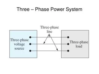
Basic Three-Phase Circuit ECE 441
What is Three-Phase Power? • Three sinusoidal voltages of equal amplitude and frequency out of phase with each other by 120°. Known as “balanced”. • Phases are labeled A, B, and C. • Phases are sequenced as A, B, C (positive) or A, C, B (negative). ECE 441
Three-Phase Power ECE 441
Definitions • 4 wires • 3 “active” phases, A, B, C • 1 “ground”, or “neutral” • Color Code • Phase A Red • Phase B Black • Phase C Blue • Neutral White or Gray ECE 441
Phasor (Vector) Form for abc Vc=Vm/+120° Va=Vm/0° Vb=Vm/-120° ECE 441
Phasor (Vector) Form for abc Vc=Vm/+120° Va=Vm/0° Vb=Vm/-120° Note that KVL applies .... Va+Vb+Vc=0 ECE 441
Three-Phase Generator • 2-pole (North-South) rotor turned by a “prime mover” • Sinusoidal voltages are induced in each stator winding ECE 441
How are the sources connected? • (a) shows the sources (phases) connected in a wye (Y). • Notice the fourth terminal, known as Neutral. • (b) shows the sources (phases) connected in a delta (∆). • Three terminals ECE 441
Look at a Y-Y System ECE 441
Definitions • Zg represents the internal generator impedance per phase • Zl represents the impedance of the line connecting the generator to the load • ZA,B,C represents the load impedance per phase • Zo represents the impedance of the neutral conductor ECE 441
Phase Voltages Line Voltages ECE 441
Vector addition to find VAB=VAN-VBN -VBN ECE 441
Using the Tip-to-Tail Method -VBN VΦ = Line-to-Neutral, or Phase Voltage VAB = VAN – VBN = √3VΦ ECE 441
Conclusions for the Y connection • The amplitude of the line-to-line voltage is equal to √3 times the amplitude of the phase voltage. • The line-to-line voltages form a balanced set of 3-phase voltages. • The set of line-to-line voltages leads the set of line-to-neutral (phase) voltages by 30°. ECE 441
Summary ECE 441
Look at the Delta-Connected Load ECE 441
Phase Currents Line Currents ECE 441
Vector Addition to find IaA=IAB-ICA -ICA ECE 441
Using the Tip-to-Tail Method -ICA IaA = √3IΦ/-30° ECE 441
Conclusions for the Delta Connection • The amplitude of the line current is equal to √3 times the phase current. • The set of line currents lags the phase currents by 30°. ECE 441