Download
1 / 24
390 likes | 834 Views
Lesson 36 AC Three Phase Power. Learning Objectives. Compute the real, reactive and apparent power in three phase systems Calculate currents and voltages in more challenging three phase circuit arrangements. Apply the principles of Power Factor Correction to a three phase load. Review.

E N D
Learning Objectives • Compute the real, reactive and apparent power in three phase systems • Calculate currents and voltages in more challenging three phase circuit arrangements. • Apply the principles of Power Factor Correction to a three phase load.
Review AC Power Summary
Review Power Triangle • The power triangle graphically shows the relationship between real (P), reactive (Q) and apparent power (S).
Active Power to Wye (Y) Load Y-load Single phase of Y-load
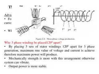
Active Power (P) to Wye (Y) Load • Because we are considering a balanced system, the power per phase (P) is identical and the total active power (PT) is simply PT = 3 P. • Using line voltage () and line current (IL=I):
Example Problem 1a EAN = 277-30 V . Compute PΦ, PT.
S Q = V I sin P Reactive Power (Q) to Wye (Y) Load • The reactivepower per phase (Q) is given
Reactive Power (Q) to Wye (Y) Load • Because we are considering a balanced system, the power per phase (Q) is identical and the total reactive power (QT) is simply QT = 3 Q. • Using line voltage (VL ) and line current (IL):
Example Problem 1b EAN = 277-30 V . Compute QΦ, QT.
Apparent Power (S) to Wye (Y) Load • The apparentpower per phase (S) is given S = VI Q P
Power Factor (FP) • The power factor (FP) is given S Q P
Example Problem 1c EAN = 277-30 V . Compute SΦ, ST, and FP.
Power to a Delta () Load -load Single phase of -load
Active Power (P) to Delta () Load • Total active power (PT) is simply PT = 3 P. • Using line voltage (VL=V) and line current ( ): • Which was the EXACT same equation as for Y loads
Reactive and apparent power to Delta (Δ) Load • The equations for calculating total reactive and apparent power are also identical to the Wye load versions:
Example Problem 2a EAN=120-30 V. Determine per phase and total power (active, reactive, and apparent). Determine total powers (active, reactive, and apparent) by multiplying the per-phase powers by 3.
Example Problem 2b EAN=120-30 V. Determine total powers (active, reactive, and apparent) by using these formulas:
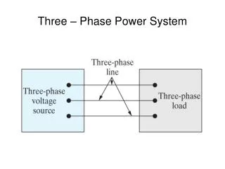
Power in Advanced 3 phase You must pay attention to the problem statement! Does it ask for total or per-phase power? What kind of power? S, P, or Q? Where is the power? Generator Line Impedances Load Pline=? Qline =? Sload =? Pload =? Qload =? Sgen=? Pgen=? Qgen=?
Power Factor Power factor (FP) tells us what portion of the apparent power (S) is actually realpower (P). FP = P / S = cos Power factor angle = cos-1(P / S)=cos-1(FP) For a pure resistance, = 0º For a pure inductance, = 90º For a pure capacitance, = -90º Review NOTE: is the phase angle of ZT, not the current or voltage.
Power Factor Correction In order to cancel the reactive component of power, we must add reactance of the opposite type. This is called power factor correction. Review
Three Phase Power Correction Capacitors will be connected in parallel with each load phase
Power Factor Correction Solution Steps Calculate the reactive power (Q) of ONE PHASE of the load Insert a component in parallel of the load that will cancel out that reactive power e.g. If the load has QΦ=512 VAR, insert a capacitor with QΦ=-512 VAR. Calculate the reactance (X) that will give this value of Q Normally the Q=V2/X formula will work Calculate the component value (F or H) required to provide that reactance.
Example Problem 3 EAB=4800 V. Frequency 60 Hz. Determine value of capacitor which must be placed across each phase of the motor to correct to a unity power factor.