Download
1 / 33
340 likes | 642 Views
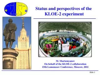
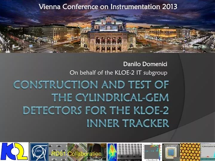
Vienna Conference on Instrumentation 2013. Danilo Domenici On behalf of the KLOE-2 IT subgroup. construction and Test of the Cylindrical-GEM detectors for the KLOE-2 Inner Tracker. The KLOE Detector at Dafne. Drift Chamber ( He/iC 4 H 10 light gas mixture)

E N D
Vienna Conference on Instrumentation 2013 Danilo Domenici On behalf of the KLOE-2 IT subgroup construction and Test of the Cylindrical-GEMdetectors for the KLOE-2 Inner Tracker
The KLOE Detector at Dafne • Drift Chamber (He/iC4H10 light gas mixture) • EM Calorimeter (Pb/SciFi, excellent time resolution) • 0.52 T Magnetic Field (Superconductive coil) • Dafne factory (e+e- at 1020 MeV and Lint=10fb-1/y) D. Domenici – INFN-LNF
KLOE-2 Upgraded QCAL LET InnerTracker 3 new detectors will be inserted before summer: • Photon taggers (HET/LET for γγ interactions) • Low angle Calorimeters (CCAL/QCAL to improve solid angle coverage) • Inner Tracker (to improve vertex resulution) resolution on KS ππ vertex from cS to cS/3 D. Domenici – INFN-LNF
Read-out Anode 2 mm GEM 3 2 mm GEM 2 2 mm GEM 1 3 mm Cathode Induction Transfer 2 Transfer 1 Conversion & Drift Cylindrical-GEM Inner Tracker FEE boards Cylindrical Triple GEM 4 layers at 13/15.5/18/20.5 cm from IPand 700 mm active length rφ 250 µm andz 400 µm in 0.42 T magnetic field XV strips-pads readout (20o÷30o stereo angle) 2% X0total radiation length in the active region D. Domenici – INFN-LNF
Layout of the GEM foil 700 mm • First batch ever produced with a single-mask etching technique developed by CERN-TE-MPE-EM and RD51 to produce large area foils • The top side of the active area is divided in 40 sectors • The HV connections are grouped in 4 tails that are directly connectorized • Each sector can be set to down voltage, ground or float by an external jumper 300 ÷ 430 mm gas holes pinholes D. Domenici – INFN-LNF
GEM foils Quality Test GEM istested in a N2 flushed plexiglass box to reduce RH below 10% Each Sector must draw a current < 1nA @ 600V Discharge rate is measured over a period of ~1h few sectors with current > 1 nA @600 V Discharge rate @600 V D. Domenici – INFN-LNF
Manufacturing a C-GEM Alignement pinholes Vacuum holes Alignement pinholes Vacuum holes 3 GEM foils are spliced together with a 3 mm overlap and closed in a vacuum bag (0.9 bar) Epoxy glue is distributed by hand on a 2 mm wide line D. Domenici – INFN-LNF
Manufacturing a C-GEM GEM is protected with a Mylar sheet and wrapped on the cylindrical mold Transpirant tissue is placed around to distribute vacuum Final cylindrical GEM with internal and external rings Vacuum bag is closed D. Domenici – INFN-LNF
Manufacturing the Cathode Nomex honeycomb is glued on the cathode foil Inner layer is glues on the mold Cathode is rolled on the mold and glued in a vacuum bag Final electrode D. Domenici – INFN-LNF
The Readout Electrode X strip Readout plane is realized at CERN TE-MPE-EM as a kapton/copper multilayer flexible circuit. It provides 2-dimensional readout with XV strips on the same plane • X are realized as longitudinal strips • V are realized by connection of pad through conductive holes and a common backplane • Pitch is 650 µm for both V strip X pitch 650µm X res 190µm (250µm @ B=0.5T) Vpitch 650µm Y res 350µm D. Domenici – INFN-LNF
Manufacturing the Readout 1k strips 1M pads is rolled over the mold Readout circuit obtained by splicing 3 foils …glued… …and closed in a vacuum bag D. Domenici – INFN-LNF
Readout CF Lamination • Then the circuit is shielded with with a very ligth Carbon fiber composite structure realized by an external company (RiBa Composites, Faenza, IT) • The shield is composed by a sandwich of two 90 µm thick carbon foils prepreg with epoxy spaced by a 5 mm thickNomexhoneycomb first 90µm CF skin 5mm HC second 90µm CF skin final readout electrode curing 24h in autoclave D. Domenici – INFN-LNF
Fixing of the PEEK Spacing Grid • To avoid possible relaxation of the gaps due e.g. to thermal expansion of the foils, we fix a spacing grid on the GEMs (only for Layers 3 and 4) • It is realized by assembling 8 rings and 12 rods of 300 µm thick PEEK PEEK grid assembled grid fixed on the GEM D. Domenici – INFN-LNF
Assembling a Triple-GEM A Vertical Insertion Machine is used to assemble the 5 electrodes of a Cylindrical-GEM Anode GEM The GEM isplaced on the Machinewithitsmold The Readout is moved down around the GEM Everythingisalignedwithanaxialprecisionof ≈0.1mm/1.5m D. Domenici – INFN-LNF
Assembling Details Detector is sealed by an epoxy flow Insertion machine isrotated to seal both sides Internal GEM surface with the anular FR4 flange Final C-GEM detector D. Domenici – INFN-LNF
4 IT Layers Completed Layer 4 Layer 3 • The 3 innermost Layers have been completed and testedwith β source and cosmic rays • The Layer4 has been closed last week • At the end of February the 4 layers will be inserted one into another and mounted on the Dafne beam pipe Layer 2 Layer 1 FEE boards with Gastone chip D. Domenici – INFN-LNF
IT FEE: Gastone Chip 128 channels GASTONE Board • Mixed analog-digital circuit • Low input equivalent noise, low power consumption and high integrated chip • 4 blocks: • charge sensitive preamplifier • shaper • leading-edge discriminator • monostable Visit the Gastone poster by Flavio Loddo D. Domenici – INFN-LNF
Test Setup • All the detectors have been tested with a cosmic-ray test-stand equipped with an external Tracking System provided by 3 planar GEMs 10x10 cm2 • Final signal and HV cables, FEE and DAQ systems have been used in the tests • The test-stand is also equipped with a 90Sr movable source to perform fast measurements without tracking D. Domenici – INFN-LNF
Space Resolution • Space resolution has been measured as a function of a transverse Magnetic Field to reproduce the KLOE situation • In the bending plane the electrons are spreaded by the field with a consequent increase of space resolution • At the KLOE field of 0.52 T the resolution rφ 250 µm is still within the experiment requirement • The field effect is not visible in the non-bending plane as expected KLOE field 0.52 T • r-φresolution (bending plane) • Z resolution D. Domenici – INFN-LNF
Blocking Capacitor on GEM3 Down • The capacitive coupling between the GEM3 Down and the Readout plane could result in induced currents causing high-multiplicity «splash events» • The effect is strongly suppressed by coupling the GEM3 Down to Ground through a series RC circuit with large capacitance and small resistance without BC C = 2.2 nF R = 10 Ω D. Domenici – INFN-LNF
Layer 1 Source Scan The profile of the source in 6 different positions is reconstructed by triggering the DAQ with a clock signal This fast test allows to check the cabling and the uniformity of the detector D. Domenici – INFN-LNF
Layer 1 Cosmics Cosmics hits are reconstructed by requiring a track in the 3 planar GEMs D. Domenici – INFN-LNF
Layer 2 Cosmics Z vs X (Lego View) noise cosmic tracks D. Domenici – INFN-LNF
Layer 3 Cosmics D. Domenici – INFN-LNF
Layer 3 Cosmics D. Domenici – INFN-LNF
First C-GEM Workshop • Last October in Frascati we organized a Cylindrical GEM Mini-workshop dedicated to this novel technology • Among the participants there were: • Rui de Oliveira from CERN workshop where the GEM foils are produced • Qun Ouyang from IHEP Beijing • Lev Shekhtman from INP Novosibirsk • A very strong interest have been shown by our chinese and russian collegues to exploit the Cylindrical GEM technology on the future upgrades of the BESIII and VEPP2000 experiments D. Domenici – INFN-LNF
Conclusions • We exploited the intrinsic lightness and flexibility of a GEM detector to build a fully cylindrical Inner Tracker without frames in the active area and an X0≈ 2% • After more than one year of construction time we have completed the 4 Layers that will be mounted as upgrade of the KLOE detector • The detectors have been extensively tested showing a good operational stability and the expected performance • We are collaborating with other groups that have expessed interest on Cylindrical GEMs in order to improve such technology and expand its operational field D. Domenici – INFN-LNF
SPARES D. Domenici – INFN-LNF
Material Budget The KLOE-2 requirement of X0 < 2% is fulfilled D. Domenici – INFN-LNF
Closing of the Last Layer D. Domenici – INFN-LNF
Gain and Discharges • Gas gain measurement performed in current mode using as normalization a refernce detector with known gain • Discharge measurement performed with a 141Am αsource • KLOE2 chosen mixture Ar/Isobuthane(90/10) is compared with the standard gas mixture Ar/Co2 (70/30) • Our working gain will be 2 x 10⁴ D. Domenici – INFN-LNF
Readout Quality Control Made by a 100 psprecision Time Domain Reflectometer Transmission line length and its damages evaluated by measuring the delay of the reflected signal Shorts V Strip# D. Domenici – INFN-LNF
IT Layers D. Domenici – INFN-LNF