Download
1 / 34
340 likes | 495 Views
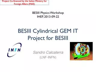
Erika De Lucia for the KLOE-2 Inner Tracker Group. Status of Cylindrical-GEM project for the KLOE-2 Inner Tracker. The KLOE-2 Inner Tracker Group. G. De Robertis , N. Lacalamita , R. Liuzzi , F. Loddo , M. Mongelli , A. Ranieri , V. Valentino INFN Bari, Bari, Italy

E N D
Erika De Lucia for the KLOE-2 Inner Tracker Group Status of Cylindrical-GEM project for the KLOE-2 Inner Tracker
The KLOE-2 Inner Tracker Group G. De Robertis, N. Lacalamita, R. Liuzzi, F. Loddo, M. Mongelli, A. Ranieri, V. Valentino INFN Bari, Bari, Italy G. Morello, M. Schioppa INFN Cosenza, gruppocollegato LNF, Cosenza, Italy A. Balla, G. Bencivenni, S. Cerioni, P. Ciambrone, E. De Lucia, D. Domenici, J.Dong, G. Felici, M. Gatta, M. Jacewicz, S. Lauciani, V. Patera, M. Pistilli, L. Quintieri, E. Tshadadze LaboratoriNazionalidiFrascati - INFN, Frascati, Italy A. Di Domenico, M. Capodiferro, A. Pelosi INFN Roma, Roma, Italy Erika De Lucia -- Vienna Conference on Instrumentation, 15-20 February 2010
7m 6 m KLOE at DAFNE f-factory • Lead/scintillating fiber • 98% coverage of solid angle • 88 modules (barrel + end-caps) • 4880 PMTs (two side read-out) • 4 m diameter × 3.3 m length • 90% helium, 10% isobutane • 12582/52140 sense/tot wires • All-stereo geometry KS = 0.6 cmKL = 340 cm K = 95 cm Drift Chamber Electromagnetic Calorimeter sE /E = 5.4%/ st = 54 ps/ srf= 150 mm sz = 2 mm sV = 3 mm sp /p = 0.4 % • 50 ps(calib) B = 0.52 T Erika De Lucia -- Vienna Conference on Instrumentation, 15-20 February 2010
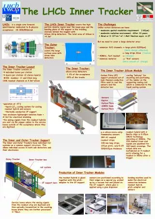
Read-out Anode 2 mm GEM 3 2 mm GEM 2 2 mm GEM 1 3 mm Cathode Induction Transfer 2 Transfer 1 Conversion & Drift KLOE-2 Inner Tracker Upgrade • For fine vertex reconstruction of Ks , η and η’ rare decays and • Ks- KLinterference measurements : • rφ 200 µm and z 500µm • low material budget:<2%X0 • 5 kHz/cm2 rate capability Cylindrical Triple GEM Cylindrical GEM detector is the adopted solution • 5 CGEM layers with radii from 13to 23 cm from IP and before DC Inner Wall • 700 mm active length • XV strips-pads readout (40o stereo angle) • 1.5% X0total radiation length in the active region with Carbon Fiber supports KS → p pvertexresolutionwillimproveofabout a factor 3 from present 6mm Erika De Lucia -- Vienna Conference on Instrumentation, 15-20 February 2010
The IT with CGEM technology The CGEM is a low-mass, fully cylindrical and dead-zone-free GEM based detector: no support frames are required inside the active area The main steps of the R&D project: Construction and complete characterizationof a full scaleCGEM prototype Study the XV stripreadoutconfiguration and itsoperation in magneticfield Construction and characterizationof a large area GEMrealizedwith the newsingle-maskphotolitografictechnique (KLOE2 IT needs GEM foilaslargeas 450x700mm2) Technical Design Report of the Inner Tracker for the KLOE-2 experiment [arXiv:1002.2572] Erika De Lucia -- Vienna Conference on Instrumentation, 15-20 February 2010
(1) CGEM prototype: construnction 2 3 1 960 mm 352 mm Full sensitive and Ultra-light detector Distribution of epoxy on foil edge 3 spliced foils ~1000mm long Cylindrical mould in vacuum bag Cylindrical GEM foil Cylindrical Cathode with annular fiberglass support flanges Proto0.1: Ø=300mm,L=350mm; 1538 axial strips, 650 µm pitch 5 4 Erika De Lucia -- Vienna Conference on Instrumentation, 15-20 February 2010
GASTONE: the IT dedicated FEE chip • Mixed analog-digital circuit (KLOE-2 dedicated); • Low input equivalent noise, low power consumption and high integrated chip; • 4 blocks: 0.35 CMOS technology- no Rad-Hard • charge sensitive preamplifier • shaper • leading-edge discriminator (prog. thr.) • monostable (stretch digital signal for trigger) 16-chs GASTONE prototype Erika De Lucia -- Vienna Conference on Instrumentation, 15-20 February 2010
(1) CGEM prototype: test-beam MDTs MDTs 10 GeVpion beam CERN-PS T9 area Efficiency ε = 99.6% Gas: Ar/CO2 = 70/30 Fields: 1.5/2.5/2.5 /4 kV/cm VGEM: 390-380-370 =1140V, gain~2·104 FEE: 16-channels GASTONE [NIMA 604 (2009)] Trigger: 2x8-MDT stations--ExternalTracking Overall detector stretching load 50 kg [NSS Conf. Rec.(2009)] Spatial Resolution (GEM)=(250µm)2 – (140µm)2 200µm Erika De Lucia -- Vienna Conference on Instrumentation, 15-20 February 2010
X pitch 650 µm 40° V pitch 650 µm 1000 µm XV (2) XV readout and magnetic field • A 10x10 cm2 Planar GEM w/650 µm pitch XV strips • has been realized and tested in magnetic field: • X-view will provide r-φ coordinate in CGEM • V-view made of pads connected by internal vias and with ~40°stereo angle • XV crossing will provide z coordinate in CGEM • readout w/GASTONE Erika De Lucia -- Vienna Conference on Instrumentation, 15-20 February 2010
(2) XV readout and magnetic field The effect of the magnetic field is twofold: a displacement (dx) and a spread of the charge over the readout plane(effect visible only on the “bending plane”) Garfield Simulation Ar/CO2=70/30 and B=0.5 T averageLorentz angle αL = 8°- 9° dx = 700 mm sdx= 200 mm Erika De Lucia -- Vienna Conference on Instrumentation, 15-20 February 2010
Y X BEAM (2) XV readout : test beam • H4 beam-line at CERN-SPS: 150 GeVpions • Goliath Magnet: dipole field up to 1.5Tin a~3x3x1m3 • Semi-permanent setup for RD51 users Gas: Ar/CO2 = 70/30 Fields: 1.5 - 3.0 - 3.0 - 5.0 kV/cm VGEM: 390-380-370 =1140V, gain~2·104 FEE: GEMs partially equipped with 22 GASTONE boards Trigger: 6 scintillators with SiPM (3 upstream, 3 downstream) External Trackers: 4 planar GEMs w/650 µm pitch XY strips X-Y GEMs X-V GEM Erika De Lucia -- Vienna Conference on Instrumentation, 15-20 February 2010
B field (2) B-induced displacement In our configuration the magnetic field effect is mainly present on the X-view • Align the setup with B = 0 • Turn on B field • Track reconstruction using the 4 X-Y GEMs (likewise oriented) • Measure the displacement on the X-V GEM (reversed wrt the other GEMs) D = 2 dx tan(θL) = D∕ 2r ( r = effective detector thickness) Erika De Lucia -- Vienna Conference on Instrumentation, 15-20 February 2010
(2) B-induced displacement Distribution of dx = D (measured displacement)/2 as a function of B field The blue point is the displacement value from GARFIELD simulation at B=0.5T KLOE magnetic field Erika De Lucia -- Vienna Conference on Instrumentation, 15-20 February 2010
(2) Spatial resolution: X-view sx= 370 mm KLOE B - field sx= 200 mm CGEM r-φresolution Erika De Lucia -- Vienna Conference on Instrumentation, 15-20 February 2010
(2) Spatial resolution : Y coordinate The Y coordinated is measured from the crossing of X and V views sY= 370 mm KLOE B - field CGEM zresolution Erika De Lucia -- Vienna Conference on Instrumentation, 15-20 February 2010
(2) Efficiency vs B field and Gain At workingpoint, VG = 1140 Volt, G~2x10⁴, efficiencydropisnegligiblefor B < 0.5 T working point The increase of the magnetic field, increasing the spread of the charge over the readout strips (less charge is collected by each single pre-amp channel) results in an efficiency drop, thus requiring for higher gain to efficiently operate the detector. Erika De Lucia -- Vienna Conference on Instrumentation, 15-20 February 2010
(3) Large Area GEM: Planar Prototype 70x30 cm2 Triple-GEM planar Single-mask foils using latest CERN technique (M. Villa) for quality and uniformity test & equipped with GASTONE 64-channels final release Cathode PCB GEM1 GEM2 GEM3 1.5x2.5 cm2 pad readout PCB GASTONE 64-chs Erika De Lucia -- Vienna Conference on Instrumentation, 15-20 February 2010
Off Gastone Electronic (OGE) Board FPGA based board Xilinx VIRTEX 4FX • Manages 1024 channels (8 Gastone Boards) • 10 serial-link (100Mb/s) read-out • zero suppression algorithm and L1 event building • Interface • Gigabit Ethernet and USB • for monitor and debug • 2Gbit/s optical link for: • DAQ data transmission • Trigger signal • Slow Control commands Erika De Lucia -- Vienna Conference on Instrumentation, 15-20 February 2010
(3) Large Area GEM: Tools & Simulation Finite element simulation (ANSYS) with 1 kg/cm, indicates a maximum gravitational+electrostatic sag of the order of 20 μm (O(5 μm ) electrostatic only) Meters [NIMA doi:10.1016/j.nima.2009.06.063] Load Cells Jaws A very large tensioning toolhas been designed. The frame gluing will be performed by using the “vacuum bag” technique, tested in the construction of the CGEM Erika De Lucia -- Vienna Conference on Instrumentation, 15-20 February 2010
Finalizing the project ANSYS finite element 3-D simulation of the CGEM to estimate structural response under tensile loads: induced strain, stress and displacements • Material characterization to implement accurate description of mechanical behavior: • Model validation by comparison with • CGEM and PGEM prototypes Simulation of 700 mm length CGEM 40 mm maximum radial displacement Kapton connects two more rigid structures radially displaced S-shaped deformation gravitational sag O(mm) Erika De Lucia -- Vienna Conference on Instrumentation, 15-20 February 2010
Conclusions • The CGEMfull-sizeprototypehasbeenbuilt and tested under differentconditions, validating the new detector idea • The finalXV readoutconfigurationhasbeensuccesfullytested in magneticfieldwithsmall planar GEMs • We are goingtobuild a large(70x30 cm2) planar GEM prototypeto test its quality and homogeneity and GASTONE 64-channels FEE and OGE Board • The project of the KLOE-2 InnerTrackerhasbeenrecentlyapproved : itsconstructionwill start in 2010 tobereadyforinsertion in the KLOE detector bysummer 2011 Erika De Lucia -- Vienna Conference on Instrumentation, 15-20 February 2010
SPARE SLIDES Erika De Lucia -- Vienna Conference on Instrumentation, 15-20 February 2010
CGEM characterization with X-ray Test • CGEM in current mode • 10x10cm2 GEM as reference (for pressure/temperature effects) • Gain and electron transparency measurements were performed • Uniformity measurement throughout the whole CGEM surface 6 keV X-ray gun Ref GEM Erika De Lucia -- Vienna Conference on Instrumentation, 15-20 February 2010
C-GEM characterization with X-ray Test • The standard GEM gas mixture is Ar/CO2 =70/30 • The detector is being flushed with a Ar/ iC4H10 / CF4 = 65 / 7 / 28gas mixture (already characterized by LHCb GEM group) • CF4 helps to match the fast electronics available at the moment (ASDQ) • Isobutane makes safer the detector operation • Gas gainmeasured up to 20000 • No discharges or leakage currents observed Ar - iC4H10 - CF4 Erika De Lucia -- Vienna Conference on Instrumentation, 15-20 February 2010
C-GEM characterization with X-ray Test GEM polarization: 375/365/355 V Norm. gain Drift field Erika De Lucia -- Vienna Conference on Instrumentation, 15-20 February 2010
C-GEM characterization with X-ray Test GEM polarization: 375/365/355 V Norm. gain Transfer fields Erika De Lucia -- Vienna Conference on Instrumentation, 15-20 February 2010
C-GEM characterization with X-ray Test GEM polarization: 375/365/355 V Norm. gain Induction field Erika De Lucia -- Vienna Conference on Instrumentation, 15-20 February 2010
(2) XV readout: Cluster size measurements X-view V-view The two strips view are well equalized The cluster sizeincreasesasmagneticfieldincreasesbecauseof the larger spread ofelectrons in the gas gaps X-view Erika De Lucia -- Vienna Conference on Instrumentation, 15-20 February 2010
Gastone Front-End Board (120 chs) Erika De Lucia -- Vienna Conference on Instrumentation, 15-20 February 2010
Large GEM R&D : single vs double mask Starting raw material: 50μm Kapton foil with 5μm Copper clad Photoresist deposition, Single Mask Hole is opened with metal and kapton etching on one side Bottom side metal etching. Top side metal is preserved with Cathodic Protection technique Back to kapton etching to get almost cylindrical shaped hole Further metal etching to form a small rim and eventually to reduce the copper thickness Erika De Lucia -- Vienna Conference on Instrumentation, 15-20 February 2010
NEW GEM 70 60/65 R&D large GEM: single vs double With an X-ray gun, we compared, in CURRENT MODE, the basic performance of the new single-mask GEM with the standard double-mask. CONICAL vs BI-CONICAL STD GEM 70 50 70 Erika De Lucia -- Vienna Conference on Instrumentation, 15-20 February 2010
R&D large GEM: single vs double Electron collection efficiency 80% at 0 Field: larger Optical Transparency due to larger diameter. Difference between the two orientations of the single mask. VGEM = 400V Ed = 1.5kV/cm Erika De Lucia -- Vienna Conference on Instrumentation, 15-20 February 2010
R&D large GEM: single vs double Extraction efficiency & Charge Sharing Equal Sharing Field highly dependent on GEM orientation for the single mask GEMs. 4.6kV/cm 5.7kV/cm VGEM = 400V Ed=1.5kV/cm 5.2kV/cm Erika De Lucia -- Vienna Conference on Instrumentation, 15-20 February 2010
70 70 50 60/65 70 single mask conical /quasi-cylindrical double mask double conical R&D on large GEM (GDD-CERN group + R.de Oliveira) Max size= 400x400 mm2 Max size= >1000x400 mm2 Gas Gain G60-70 / Gstd = 0.67 G70-60 / Gstd = 0.80 Additional 10 20 V needed to operate at the same Gain as Standard GEM Erika De Lucia -- Vienna Conference on Instrumentation, 15-20 February 2010