Download
1 / 16
160 likes | 353 Views
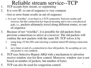
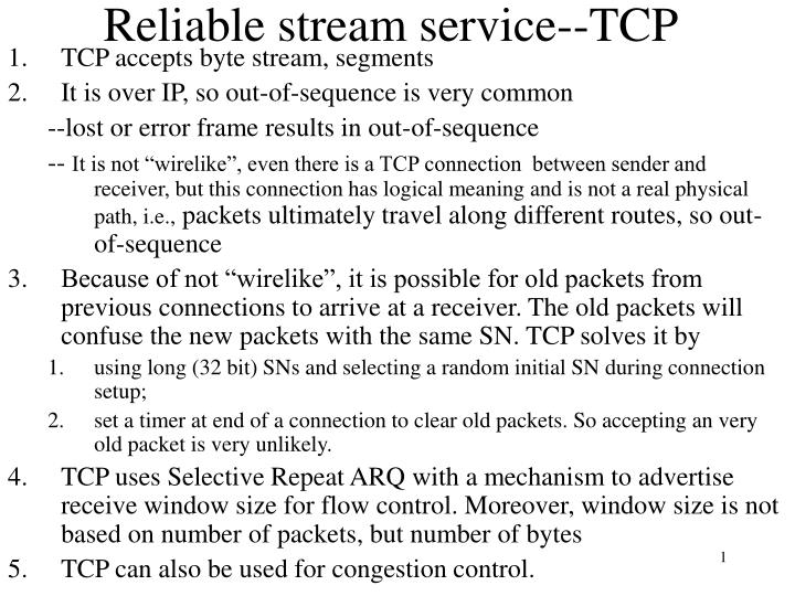
Reliable stream service--TCP. TCP accepts byte stream, segments It is over IP, so out-of-sequence is very common --lost or error frame results in out-of-sequence

E N D
Reliable stream service--TCP • TCP accepts byte stream, segments • It is over IP, so out-of-sequence is very common --lost or error frame results in out-of-sequence -- It is not “wirelike”, even there is a TCP connection between sender and receiver, but this connection has logical meaning and is not a real physical path, i.e., packets ultimately travel along different routes, so out-of-sequence • Because of not “wirelike”, it is possible for old packets from previous connections to arrive at a receiver. The old packets will confuse the new packets with the same SN. TCP solves it by • using long (32 bit) SNs and selecting a random initial SN during connection setup; • set a timer at end of a connection to clear old packets. So accepting an very old packet is very unlikely. • TCP uses Selective Repeat ARQ with a mechanism to advertise receive window size for flow control. Moreover, window size is not based on number of packets, but number of bytes • TCP can also be used for congestion control.
Application Application byte stream byte stream Segments Transmitter Receiver Receive buffer Send buffer ACKs TCP preview—reliable stream service Figure 5.32
Transmitter Receiver Send Window Receive Window Slast + Wa-1 Rlast + WR – 1 Rlast ... ... ... Rnext Rnew octets transmitted & ACKed Slast Slast + Ws – 1 Srecent Rlast highest-numbered byte not yet read by the application Rnext next expected byte Rnew highest numbered byte received correctly Rlast+WR-1 highest-numbered byte that can be accommodated in receive buffer Slast oldest unacknowledged byte Srecent highest-numbered transmitted byte Slast+Wa-1 highest-numbered byte that can be transmitted Slast+Ws-1 highest-numbered byte that can be accepted from the application Wa=Wr-(Rnew-Rlast), Srecent-Slast<=Wa Advertised window:
Data link protocols • Framing: indicate the boundaries of frames • Error control: ensure reliable transmission • Flow control: prevent sender from overrunning receiver • Addressing information: is required when the channel carries information for multiple users. • Assumption: data link is “wirelike”. • Two protocols: HDLC and PPP.
HDLC data link control • Was set by ISO • Is connection-oriented: set up connection first, then transfer frames using one of three ARQs, finally tear down the connection (Note: LAN generally provides unacknowledged connectionless service) • HLDC configurations and transfer modes • HDLC frame format • Typical frame exchange
Data link layer NLPDU Network Layer Network Layer “packet” DLSAP DLSDU DLSDU DLSAP DLPDU Data Link Layer Data Link Layer “frame” Physical Layer Physical Layer Figure 5.32
HDLC configurations and transfer modes Unbalanced Point-to-point link Commands Primary Secondary Responses NRM: Normal Response Mode Unbalanced Multipoint link Commands Primary Responses Secondary Secondary Secondary Balanced Point-to-point link between Combined Stations Commands Secondary Primary Responses Primary Secondary Commands Responses ABM: Asynchronous Balance Mode Figure 5.33
HDLC frame format Flag Address Control Information FCS Flag • Framing: Flags at both ends define the frame boundaries. • Flag value is 01111110 • 2. Addressing: indicate the destination address • 3. Control: various control fields to indicate different frames • 4. Information: user information by bits, generally no length limit. • 5. FCS: Frame Check Sum, using 16-or 32-bit CRC Question: flag value 01111110 may appear in frame, what to do? Solution: bit stuffing, a technique to prevent occurrence of flag. sender inserts an extra 0 after each instance of five consecutive 1s. receiver looks for five consecutive 1s, if followed by 0, then this 0 is stuffed and is removed; if followed by 10, then flag found. Example: 0110111111111100 011011111011111000 where 0 is stuffed 011011111-11111-00 where –: removed stuff 0 Figure 5.35
Control field format: three types of frames Information Frame or I-frame 1 5 2-4 6-8 N(R) 0 N(S) P/F Supervisory Frame or S-frame 1 N(R) 0 S S P/F Unnumbered Frame or U-frame 1 1 M M M M P/F M P/F bit: Poll/Final bit. If set, the frame is a poll frame from primary or the last I-frame of all transmitted frames. N(S): sender SN of I-frame, N(R): piggybacked ACK Window size: 23 –1 = 7 for Stop-and-Wait and Go-back-N, 4 for Selective-Repeat (in extended control field) 27 –1 = 127 for the first two ARQs, 64 for the last ARQ
Control field format: S-frame and U-frame Four types of S-frames: SS=00: RR (Receive Ready) frame used when no I-frame for piggyback SS=01: REJ (Reject) frame, i.e., NAK frame SS=10: RNR (Receive Not Ready) frame, indicate unable to receive any more. SS=11: SREJ (Selective Reject) frame, indicate the retransmission of specified frame Supervisory Frame or S-frame 1 N(R) 0 S S P/F Unnumbered Frame or U-frame 1 1 M M M M P/F M U-frames for setup or release of connection: SABM (Set Asynchronous Balance Mode) SNRM (Set Normal Response Mode) SABME: SABM Extended SNRME: SNRM Extended DISC (DISConnect) UA (Unnumbered acknowledgment) FRMR (Frame Reject) Figure 5.36
Typical frame exchange—for connection setup and release Data transfer SABM UA UA DISC Figure 5.37
Typical frame exchange— using normal response mode Secondaries B, C Primary A B, RR, 0, P B, I, 0, 0 B, I, 1, 0 X B, I, 2, 0,F B, SREJ, 1 C, RR, 0, P C, RR, 0, F B, SREJ, 1,P B, I, 1, 0 B, I, 3, 0 B, I, 4, 0, F B, I, 0, 5 What ARQ? Selective repeat (Des.-IP, frame-type, N(S) (for I-frame), N(R), P/F) Figure 5.38
Typical frame exchange— using asynchronous balanced mode Combined Station A Combined Station B B, I, 0, 0 A, I, 0, 0 B, I, 1, 0 A, I, 1, 1 X A, I, 2, 1 B, I, 2, 1 B, I, 3, 2 B, REJ, 1 B, I, 4, 3 A, I, 3, 1 B, I, 1, 3 B, I, 2, 4 B, RR, 2 B, I, 3, 4 B, RR, 3 What ARQ? Go-back-N Figure 5.39
Point-to-Point protocol • Used to connect: • Router to router, or home PC to ISP. • HDLC-like frame format • Information by bytes, so char-stuffing in case a flag byte appears in information • Support multiple network protocols simultaneously, e.g, IP, IPX( Novell NetWare) etc. • LCP (Link Control Protocol): set up, configure, test, maintain, and terminate a link connection • NCP (Network Control Protocol): configure each network protocol, specifically, NCP for IP performs dynamical IP address assignment • PAP (Password Authentication Protocol): login ID and password • CHAP (Challenge-Handshake Authentication Protocol): no plain password goes between two peers.
PPP frame format flag Address Flag Control Protocol Information CRC 01111110 01111110 1111111 00000011 All stations are to accept the frame Specifies what kind of packet is contained in the payload, e.g., LCP, NCP, IP, OSI CLNP, IPX Unnumbered frame • Framing flag: same as HDLC • Address: 1111111, broadcast address, no need for specific host address • Control: default for connectionless transfer, not use sequence number • Protocol: support multiple network protocols • Information: byte-based, not bit-based. So Char-stuffing, • see Problem 5-54. • 6. CRC: check sum Figure 5.40
A Typical Scenario 1. Carrier Detected Dead 7. Carrier Dropped Home PC to Internet Service Provider 1. PC calls router via modem. 2. PC and router exchange LCP packets to negotiate PPP parameters. 3. Check on identities. 4. NCP packets exchanged to configure the network layer, e.g., TCP/IP ( requires IP address assignment). 5. Data transport, e.g. send/receive IP packets. 6. NCP used to tear down the network layer connection (free up IP address); LCP used to shut down data link layer connection. 7. Modem hangs up. failed Establish Terminate 2. LCP Options Negotiated 6. Done failed Authenticate 5. Open 3. Authentication Completed 4. NCP Configuration Network Figure 5.41