Download
1 / 29
290 likes | 504 Views
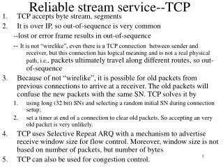
Reliable stream service--TCP. TCP accepts byte stream, so segmenting It is over IP, so out-of-sequence is very common --lost or error frame results in out-of-sequence

E N D
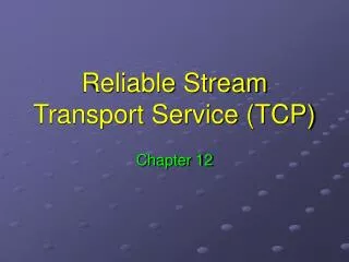
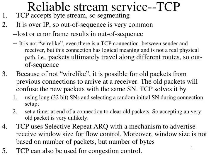
Reliable stream service--TCP • TCP accepts byte stream, so segmenting • It is over IP, so out-of-sequence is very common --lost or error frame results in out-of-sequence -- It is not “wirelike”, even there is a TCP connection between sender and receiver, but this connection has logical meaning and is not a real physical path, i.e., packets ultimately travel along different routes, so out-of-sequence • Because of not “wirelike”, it is possible for old packets from previous connections to arrive at a receiver. The old packets will confuse the new packets with the same SN. TCP solves it by • using long (32 bit) SNs and selecting a random initial SN during connection setup; • set a timer at end of a connection to clear old packets. So accepting an very old packet is very unlikely. • TCP uses Selective Repeat ARQ with a mechanism to advertise receive window size for flow control. Moreover, window size is not based on number of packets, but number of bytes • TCP can also be used for congestion control.
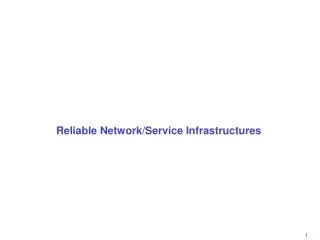
Application Application byte stream byte stream Segments Transmitter Receiver Receive buffer Send buffer ACKs TCP preview—reliable stream service CIS, IUPUI Figure 5.32
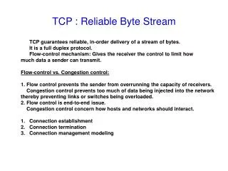
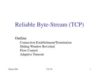
Transmitter Receiver Send Window Receive Window Slast + Wa-1 Rlast + WR – 1 Rlast ... ... ... Rnext Rnew octets transmitted & ACKed Slast Slast + Ws – 1 Srecent Rlast highest-numbered byte not yet read by the application Rnext next expected byte Rnew highest numbered byte received correctly Rlast+WR-1 highest-numbered byte that can be accommodated in receive buffer Slast oldest unacknowledged byte Srecent highest-numbered transmitted byte Slast+Wa-1 highest-numbered byte that can be transmitted Slast+Ws-1 highest-numbered byte that can be accepted from the application Wa=WR-(Rnew-Rlast), Srecent-Slast<=Wa Advertised window:
Data link protocols • Framing: indicate the boundaries of frames • Error control: ensure reliable transmission • Flow control: prevent sender from overrunning receiver • Addressing information: is required when the channel carries information for multiple users. • Assumption: data link is “wirelike”. • Two protocols: HDLC and PPP. CIS, IUPUI
HDLC data link control • Was set by ISO • Is connection-oriented: set up connection first, then transfer frames using one of three ARQs, finally tear down the connection (Note: LAN generally provides unacknowledged connectionless service) • HLDC configurations and transfer modes • HDLC frame format • Typical frame exchange CIS, IUPUI
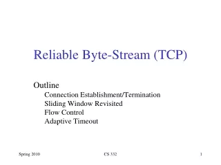
Data link layer NLPDU Network Layer Network Layer “packet” DLSAP DLSDU DLSDU DLSAP DLPDU Data Link Layer Data Link Layer “frame” Physical Layer Physical Layer CIS, IUPUI Figure 5.32
HDLC configurations and transfer modes Unbalanced Point-to-point link Commands Primary Secondary Responses NRM: Normal Response Mode Unbalanced Multipoint link Commands Primary Responses Secondary Secondary Secondary Balanced Point-to-point link between Combined Stations Commands Secondary Primary Responses Primary Secondary Commands Responses ABM: Asynchronous Balance Mode Figure 5.33
HDLC frame format Flag Address Control Information FCS Flag • Framing: Flags at both ends define the frame boundaries. • Flag value is 01111110 • 2. Addressing: indicate the destination address • 3. Control: various control fields to indicate different frames • 4. Information: user information by bits, generally no length limit. • 5. FCS: Frame Check Sum, using 16-or 32-bit CRC Question: flag value 01111110 may appear in frame, what to do? Solution: bit stuffing, a technique to prevent occurrence of flag. sender inserts an extra 0 after each instance of five consecutive 1s. receiver looks for five consecutive 1s, if followed by 0, then this 0 was stuffed and is removed; if followed by 10, then flag found. Example: 0110111111111100 011011111011111000 where 0 is stuffed 011011111-11111-00 where –: removed stuff 0 Figure 5.35
Control field format: three types of frames Information Frame or I-frame 1 5 2-4 6-8 N(R) 0 N(S) P/F Supervisory Frame or S-frame 1 N(R) 0 S S P/F Unnumbered Frame or U-frame 1 1 M M M M P/F M P/F bit: Poll/Final bit. If set, the frame is a poll frame from primary or the last I-frame of all transmitted frames. N(S): sender SN of I-frame, N(R): piggybacked ACK Window size: 23 –1 = 7 for Stop-and-Wait and Go-back-N, 4 for Selective-Repeat (in extended control field) 27 –1 = 127 for the first two ARQs, 64 for the last ARQ
Control field format: S-frame and U-frame Four types of S-frames: SS=00: RR (Receive Ready) frame used when no I-frame for piggyback SS=01: REJ (Reject) frame, i.e., NAK frame SS=10: RNR (Receive Not Ready) frame, indicate unable to receive any more. SS=11: SREJ (Selective Reject) frame, indicate the retransmission of specified frame Supervisory Frame or S-frame 1 N(R) 0 S S P/F Unnumbered Frame or U-frame 1 1 M M M M P/F M U-frames for setup or release of connection: SABM (Set Asynchronous Balance Mode) SNRM (Set Normal Response Mode) SABME: SABM Extended SNRME: SNRM Extended DISC (DISConnect) UA (Unnumbered acknowledgment) FRMR (Frame Reject) Figure 5.36
Typical frame exchange—for connection setup and release Data transfer SABM UA UA DISC CIS, IUPUI Figure 5.37
Typical frame exchange— using normal response mode Secondaries B, C Primary A B, RR, 0, P B, I, 0, 0 B, I, 1, 0 X B, I, 2, 0,F B, SREJ, 1 C, RR, 0, P C, RR, 0, F B, SREJ, 1,P B, I, 1, 0 B, I, 3, 0 B, I, 4, 0, F B, I, 0, 5 What ARQ? Selective repeat (Des.-IP, frame-type, N(S) (for I-frame), N(R), P/F) Figure 5.38
Typical frame exchange— using asynchronous balanced mode Combined Station A Combined Station B B, I, 0, 0 A, I, 0, 0 B, I, 1, 0 A, I, 1, 1 X A, I, 2, 1 B, I, 2, 1 B, I, 3, 2 B, REJ, 1 B, I, 4, 3 A, I, 3, 1 B, I, 1, 3 B, I, 2, 4 B, RR, 2 B, I, 3, 4 B, RR, 3 What ARQ? Go-back-N CIS, IUPUI Figure 5.39
Point-to-Point protocol • Used to connect: • Router to router, or home PC to ISP. • HDLC-like frame format • Information by bytes, so char-stuffing in case a flag byte appears in information • Support multiple network protocols simultaneously, e.g, IP, IPX( Novell NetWare) etc. • LCP (Link Control Protocol): set up, configure, test, maintain, and terminate a link connection • NCP (Network Control Protocol): configure each network protocol, specifically, NCP for IP performs dynamical IP address assignment • PAP (Password Authentication Protocol): login ID and password • CHAP (Challenge-Handshake Authentication Protocol): no plain password goes between two peers.
PPP frame format flag Address Flag Control Protocol Information CRC 01111110 01111110 1111111 00000011 All stations are to accept the frame Specifies what kind of packet is contained in the payload, e.g., LCP, NCP, IP, OSI CLNP, IPX Unnumbered frame • Framing flag: same as HDLC • Address: 1111111, broadcast address, no need for specific host address • Control: default for connectionless transfer, not use sequence number • Protocol: support multiple network protocols • Information: byte-based, not bit-based. So Char-stuffing, • see Problem 5-54. • 6. CRC: check sum CIS, IUPUI Figure 5.40
A Typical Scenario 1. Carrier Detected Dead 7. Carrier Dropped Home PC to Internet Service Provider 1. PC calls router via modem. 2. PC and router exchange LCP packets to negotiate PPP parameters. 3. Check on identities. 4. NCP packets exchanged to configure the network layer, e.g., TCP/IP ( requires IP address assignment). 5. Data transport, e.g. send/receive IP packets. 6. NCP used to tear down the network layer connection (free up IP address); LCP used to shut down data link layer connection. 7. Modem hangs up. failed Establish Terminate 2. LCP Options Negotiated 6. Done failed Authenticate 5. Open 3. Authentication Completed 4. NCP Configuration Network CIS, IUPUI Figure 5.41
Error Detection and Correction(Chapter 3) • Error detection and retransmission • When return channel is available • Used in Internet • Waste bandwidth • Forward error correction (FEC) • When the return channel is not available • When retransmission incurs more cost • Used in satellite and deep-space communication, as well as audio CD recoding. • Require redundancy and processing time. CIS, IUPUI
Odd error detection using parity bit • Seven data bit plus 1 parity bit • 1011010 0 • 1010001 1 • Then any odd errors can be detected. CIS, IUPUI
Two-dimension parity checks 1 0 0 1 0 0 0 1 0 0 0 1 1 0 0 1 0 0 1 1 0 1 1 0 1 0 0 1 1 1 • Several information rows • Last column: check bits for rows • Last row: check bits for columns Can detect one, two, three errors, But not all four errors. 1 0 0 1 0 0 0 0 0 0 0 1 1 0 0 1 0 0 1 1 0 1 1 0 1 0 0 1 1 1 1 0 0 1 0 0 0 0 0 0 0 1 1 0 0 1 0 0 1 0 0 1 1 0 1 0 0 1 1 1 1 0 0 1 0 0 0 0 0 1 0 1 1 0 0 1 0 0 1 0 0 1 1 0 1 0 0 1 1 1 1 0 0 1 0 0 0 0 0 1 0 1 1 0 0 1 0 0 1 0 0 0 1 0 1 0 0 1 1 1 2 errors 3 errors 4 errors 1 error CIS, IUPUI
Internet Checksum • IP packet, a checksum is calculated for the headers and put in a field in the header. • Goal is easy/efficient to implement, make routers simple and efficient. • Suppose m 16-bit words, b0, b1, …, bm-1 • Compute x= b0+ b1+ …+ bm-1 mod 216 -1 • Set checksum bm=-x • Insert x in the checksum field • Verify b0+ b1+ …+ bm-1 + bm=0 mod 216 -1. CIS, IUPUI
CRC (Cyclic Redundancy Check) (chapter 3.9.4) • Based on polynomial codes and easily implemented using shift-register circuit • Information bits, codewords, error vector are represented as polynomials with binary coefficients. On the contrary, the coefficients of a polynomial will be a binary string. • Polynomial arithmetic is done modulo 2 with addition and subtraction being Exclusive-OR, so addition and subtraction is the same. • Examples: 10110 x4 + x2 + x 01011 x3 + x + 1 CIS, IUPUI
Addition: 11000001 + 01100000 = 10100001 Multiplication: 00000011 * 00000111 = 00001001 1110 = q(x) quotient x3 + x2 + x 00001011 ) 01100000 Division: x3 + x+ 1 ) x6 + x5 1011 x6 + x4 + x3 dividend 1110 divisor 1011 x5 + x4 + x3 1010 x5 + x3 + x2 1011 3 10 35 ) 122 x4 + x2 105 x4 + x2 + x 17 x = r(x) remainder polynomial arithmetic CIS, IUPUI Figure 3.55
How to compute CRC • There is a generator polynomial, g(x) of degree r, which the sender and receiver agree upon in advance. • Suppose the information transmitted has m bits, i.e. i(x), then sender appends rzero at the end of information, i.e, xr i(x) • Perform xr i(x) / g(x) to get remainder r(x) (and quotient q(x)) • Append the r bit string of r(x) to the end of m bit information to get m+r bit string, i.e., b(x), for transmission. • b(x) = xr i(x)+ r(x) ( =g(x)q(x)+r(x)+r(x)=g(x)q(x) ) • When receiver receives the bit string, i.e., b’(x), it will divide b’(x)by g(x) , if the remainder is not zero, then error occurs. --supposeno error occurs, then b’(x) = b(x), so b’(x)/g(x) =b(x)/g(x)=g(x)q(x)/g(x)=q(x), remainder is 0. CIS, IUPUI
Example of CRC encoding x3 + x2 + x 1110 Generator polynomial: g(x)= x3 + x + 1 1011 Information: (1,1,0,0) i(x) = x3 + x2 Encoding: x3i(x) = x6 + x5 x3 + x+ 1 x6 + x5 1011 ) 1100000 x6 + x4 + x3 1011 x5 + x4 + x3 1110 1011 x5 + x3 + x2 1010 x4 + x2 1011 x4 + x2 + x x 010 • Transmitted codeword: • b(x) = x6 + x5 + x • b= (1,1,0,0,0,1,0) CIS, IUPUI Figure 3.57
Example of CRC encoding (cont.) If 1100010 is received, then 1100010 is divided by 1011, The remainder will be zero (please verify yourself), so no error. Suppose 1101010 is received, then let us do the division as follows: 1111 1011 ) 1101010 1011 1100 1011 1111 1011 1000 1011 The remainder is not zero, so error occurs. 11 CIS, IUPUI
Typical standard CRC polynomials • CRC-8: x8 + x2 + x + 1 ATM header error check • CRC-16: x16+x12+x5+1 HDLC, XMODEM, V.41 • CRC-32: x32+x26+x23+x22+ IEEE 802, DoD, V.41, x16+x12+x11+x10+ AAL5 x8+x7+x5+x4+x2+x+1 CIS, IUPUI
Analysis of error detection power Received poly: R(x)= b(x) +e(x), where e(x) is error poly. 1. Single errors: e(x) = xi0 in-1 If g(x) has more than one term, it cannot divide e(x) 2. Double errors:e(x) = xi+ xj0 i < jn-1 = xi(1 + xj-i) Fact: if p(x) is primitive of degree t, the smallest m for which 1+xm is divisible by p(x) is 2t-1. Thus, if p(x) is selected to be a primitive poly of degree t=n-k, p(x) will detect all double errors as long as the codeword length does not exceed 2n-k1. So, g(x)=(1+x)p(x), p(x) is a primitive poly. e.g. CRC-16=(1+x)(x15+x+1), it can detect all double errors as long as the codeword length is less or equal to 215-1=32767. 3. Odd number of errors:e(1) =1. If g(x) has (x+1) as a factor, then g(1) = 0 and all codewords have an even number of 1s. CIS, IUPUI Figure 3.60
ith position L error pattern d(x) 4. Error bursts of length L:0…0110 • • • •0001011000 e(x) = xi d(x) where deg(d(x)) = L-1 g(x) has degree n-k; g(x) cannot divide d(x) if deg(g(x))> deg(d(x)) • L = (n-k) or less: all will be detected • L = (n-k+1): deg(d(x)) = deg(g(x)) i.e. d(x) = g(x) is the only undetectable error pattern, fraction of bursts which are undetectable = 1/2L-2 (the first and last bit in L range must be one, the left L-2 bits must match with the coefficients in g(x). • L > (n-k+1): fraction of bursts which are undetectable = 1/2n-k CIS, IUPUI Figure 3.61
The error detection capabilities of CRCs • As long as the g(x) is selected appropriately • All single errors • All double errors • All odd number of errors • Burst error of length L, the probability that this burst error is undetectable = 1/2(L-2) • CRC can be easily implemented in hardware • One word about error correction: more powerful, but need more extra check bits, more slow, so not use as much as error detection. CIS, IUPUI