Download
1 / 10
100 likes | 268 Views
NCSX Cryostat WBS-171. Steve Raftopoulos NCSX Cryostat WBS(171) Manager. Table of Contents. Introduction Requirements Interfaces Design plans Procurement plans Risk Assessment. Introduction.

E N D
NCSX CryostatWBS-171 Steve Raftopoulos NCSX Cryostat WBS(171) Manager SC Project Review of NCSX, April 8-10, 2008
Table of Contents • Introduction • Requirements • Interfaces • Design plans • Procurement plans • Risk Assessment SC Project Review of NCSX, April 8-10, 2008 S. Raftopoulos page 2
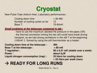
Introduction The cryostat (WBS 171) is an insulating, semi-hermetic barrier that will allow the surrounding of the stellerator core with a cold nitrogen atmosphere down to a temperature of 77K. The semi-hermetic nature of the cryostat excludes the components of atmosphere from approaching the stellerator core in the design temperature range (77K to 311K). SC Project Review of NCSX, April 8-10, 2008 S. Raftopoulos page 3
Requirements • Must be gas-tight to internal positive pressure. • Must provide penetrations for vessel extensions, electrical & hydraulic lines, stellerator supports, etc. • Shall be of demountable design. • Shall withstand vacuum boundary displacements (~1/4” radial) due to thermal expansion/contraction. • Shall withstand displacements (~1/4” radial) due to movement of the coil/coil support structure during magnet pulse. • The cryostat design, including penetrations and joint sealing, shall limit the influx of ambient heat to about 13.9 kW (includes WBS 172, machine base). • Shall be have provisions for custom configuration. • Cryostat panels shall contain a feature allowing the admission of ambient temperature nitrogen gas. • Shall be compatible with all indentified ES&H requirements and best practices. SC Project Review of NCSX, April 8-10, 2008 S. Raftopoulos page 4
Interfaces • MECHANICAL • EVERYTHING is either within or passes through the cryostat. A system interface document will address all interfaces, including planned (and unplanned) maintenance. • ELECTRICAL • Coil buss work • Signal and control cabling • ENVIRONMENTAL • Test cell (maintain environment safe for occupation) • HVAC (much nitrogen gas must be vented SC Project Review of NCSX, April 8-10, 2008 S. Raftopoulos page 5
Design Plans • The current cryostat concept has double mechanical strut located at the upper, outer, and lower aspects of each TF coil • Basic shape is described by struts on radial planes SC Project Review of NCSX, April 8-10, 2008 S. Raftopoulos page 6
Design Plans • An FRP panel bridges two struts as a substrate • A glued 16 cm pyramid of polyurethane foam is applied to the substrate SC Project Review of NCSX, April 8-10, 2008 S. Raftopoulos page 7
Design Plans • Lapped layers of flexible foam laid into the steps of the rigid foam pyramids with clamping/beauty panels finish the assembly SC Project Review of NCSX, April 8-10, 2008 S. Raftopoulos page 8
Procurement plans • In this modular panel design, components are common “off the shelf” items, readily available and inexpensive. • Design incorporates “loose” tolerances, intentionally chosen to keep costs down. “Woodworking” tolerances apply. • WAF includes hours for in-house production. SC Project Review of NCSX, April 8-10, 2008 S. Raftopoulos page 9
Risk Assessment • Low Design Maturity, High Complexity • Risk • The modular panel design places priority on flexibility and accommodates easy access to stellerator core components, but has a higher risk of incurring sealing difficulties. • Mitigation • Solicit experience from other facilities with operating cryostats. • Prototype the concepts. • Develop the cryostat in parallel with the remaining stellerator design. Make accommodations for the performance & reliability of the cryostat. • A comprehensive Failure Modes and Effects (FMEA) document that will include failures of components within the cryostat will guide the design. • Opportunity • Investigate alternative design concepts (i.e. the Alcator C-MOD design, which is a “simpler” structure that surrounds machine). SC Project Review of NCSX, April 8-10, 2008 S. Raftopoulos page 10