Download
1 / 15
200 likes | 652 Views
Cryostat. New Pulse-Tube (helium-free). Laboratory performances : Cooling-down time 30-48h Number of cooling cycles so far 12 Base T: 70-90mK Small problems at the telescope compared to lab : - have to use the maximum allowed He pressure in the pipes (OK)

E N D
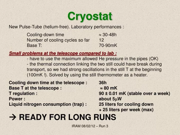
Cryostat New Pulse-Tube (helium-free). Laboratory performances : Cooling-down time 30-48h Number of cooling cycles so far 12 Base T: 70-90mK Small problems at the telescope compared to lab : - have to use the maximum allowed He pressure in the pipes (OK) - the thermal connection linking the two still could have break during transport, so we had strong oscillations in the still T at the beginning (100mK !). Solved by using the still thermometer as a heater. Cooling down time at the telescope : 36h Base T at the telescope : 80 mK T regulation : 90 ± 0.01 mK (stable over a week) Power : about 5W Liquid nitrogen consumption (trap) : 25 liters for cooling down + 25 liters per week (max) READY FOR LONG RUNS IRAM 08/02/12 – Run 3
Optics LENSES : same as 2010 (corrugated – IRAM) FILTERS : same filters, added diaphragm at 80K to (try) reduce the stray light SPLITTER : replaced the grid polarizer by a dichroic. The 2mm array is thus now in reflection, while the 1mm is in transmission. NOT OPTIMIZED AT 45 deg - REFLECTION. THE LOSS IN TRANSMISSION IS ABOUT 15%. IRAM 08/02/12 – Run 3
Arrays - electronics 2 mm : Hilbert dual-polar (NICA 8c). « Markus design » 132 pixels (12x12 array) Pixels pitch: 2.3mm 0.75F· (very close to the final design) Wafer thickness: 300m Backshort: 700m Al thickness: 20nm Cold amplifier: YEBES 1.2-1.8GHz Electronics: ROACH board (116 channels) 1.25 mm : Hilbert dual-polar (NICA 8c). « Markus design » 132 pixels (12x12 array) Pixels pitch: 2.3mm F· (planned to reduce to 1.6mm) Wafer thickness: 400m Backshort: 1100m Al thickness: 20nm Cold amplifier: Caltech SiGe 0.5-4GHz Electronics: ROACH board (116 channels) IRAM 08/02/12 – Run 3
Weather THE WEEK BEFORE : GOOD DURING THE RUN : VERY UNSTABLE BETTER TAU = 0.25-0.30 (first two nights) MOSTLY … TAU = 0.4-0.6 VERY WINDY RAIN, SNOW AFTER THE RUN : PERFECT BAD: 1.25mm BAND PARTICULARLY AFFECTED GOOD: a very limited number of hours have been subtracted to the 30-m observations. IRAM 08/02/12 – Run 3
Installed OK IRAM 08/02/12 – Run 3
Added a thick (2mm) -metal screen (cylinder) at 300K (around the cryostat). This kills by a factor of > 100 the radial B fields, by a factor about 20 the axial ones. + a superconducting (Pb) cylinder at 1K (around the still screen) Good news : B shield LARGE SLEW During this run no more « jumps » or strange (e.g. « 50 s ») disturbances from the cabin. We don’t even « see » if the chopper is ON of OFF. IRAM 08/02/12 – Run 3
Noise (2 mm) Noise around 2 Hz/Hz0.5 roughly like in 2010 IRAM 08/02/12 – Run 3
Noise (1.25 mm) Noise around 2 Hz/Hz0.5 like the 2 mm IRAM 08/02/12 – Run 3
An example (1.25 mm) Tau > 0.3 IRAM 08/02/12 – Run 3
2 mm – Preliminary sensitivity GMAur (60mJy) Quick-look map. Filtered, not decorrelated. Single scan (12 min) Conservative estimations, independently made from Xavier and Cardiff, indicate better than 20mJy·s0.5 per beam. Means roughly two times better than in 2010. Mainly thanks to the dual-pol. VERY ROUGH (pixel S/N) estimate. Response is around 80-100Hz/Jy (1.5-2kHz signal on Uranus, 20Jy). The noise was 2Hz/Hz0.5 so it seems that: S/N = 20-25 mJy/Hz0.5/pixel consistent IRAM 08/02/12 – Run 3
1.25 mm – Telescope See Xavier for real numbers. In any case, despite it’s still worse than MAMBO-2, it improved by a factor 4 with respect to RUN2. M82 - SINGLE SCAN IRAM 08/02/12 – Run 3
Wrong filter @ 1.25 mm !! Misplaced 8 cm-1 low-pass (1K) • Plans for 1.25mm (2012): • No need of band-defining • filters (using the dichroic) • New arrays. Smaller pixels • on thinner substrate (Markus) In any case not so easy to fill the entire 1mm band 2mm not bad: T > 0.2 in 125-170GHz band IRAM 08/02/12 – Run 3
Not understood … glitches - rate variable between scans (by a factor of 5). Normal rate : one point every 4-20sec (100-500 data points) above 3 sigma - decorrelated between the two arrays - correlated in the same array - one single point (26Hz) - spectrum of glitches is continuous (polinomium order 2) --> a lot of them in the noise - cosmics ?? VERY unlikely for a number of reasons. After the run, back home, we don’t see them anymore ! Red and black : 2mm array (2 pixels) Blue : 1mm array (1 pixel) IRAM 08/02/12 – Run 3
RF dIdQ photometry See Xavier and Martino. PAPER IN PREPARATION. IRAM 08/02/12 – Run 3
Still no explanations • The « plateau » in the strong sources maps. • Robert, Xavier • Electronics ? • 2) The beams distortion at the center of the arrays, in particular at 2mm. • Optics ? Effects introduced by the dichroic ? Requires more careful checks on the sky simulator . So far just used for sensitivity and pixels localisation. IRAM 08/02/12 – Run 3