Download
1 / 26
330 likes | 795 Views
Novel Ultrafast Electron Diffraction System (“streaked”-UED). Luigi Faillace. Ultrafast Electron Sources for Diffraction and Microscopy Workshop December 12 th - 14 th 2012, California NanoScience Institute at UCLA. ABOUT RADIABEAM.

E N D
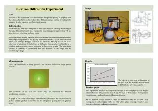
Novel Ultrafast Electron Diffraction System (“streaked”-UED) Luigi Faillace Ultrafast Electron Sources for Diffraction and Microscopy Workshop December 12th - 14th 2012, California NanoScience Institute at UCLA
ABOUT RADIABEAM RadiaBeam Technologies, LLC. is a small business with core expertise in accelerator physics. Spin-off from UCLA (2004) Extensive R&D Program (DOE, DOD, DHS, NSF) Growing products line for research laboratories and industrial customers (magnets, diagnostics, RF structures, complete systems) Ultrafast Electron Sources for Diffraction and Microscopy Workshop
Customers Ultrafast Electron Sources for Diffraction and Microscopy Workshop
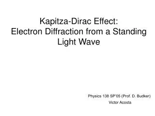
Ultrafast Electron Diffraction Ultrafast electron diffraction (UED) has the potential for real-time imaging of structural changes on atomic length scales, thus promising to make a profound impact on a large area of science including biology, chemistry, nano and material sciences [*] x x x x x x Pegasus pump and probe setup o o RF gun UCLA/BNL/SLAC 6 MW 2.856 GHz o o o Two axes x-y sample-holder movement o Probing electron beam ~200 fs rms long 1 pC 3.5 MeV e- beam 12 bit camera f/0.95 lens coupling Lanex screen or MCP detector IR laser pulse 1-10 mJ 40 fs rms Collimating hole 1mm diameter Pump pulse 0.5 mJ 800 nm 0.1 mJ 400 nm 40 fsrms *P. Musumeci et al., Relativistic electron diffraction at the UCLA Pegasus photoinjectorlaboratory, Ultramicroscopy108 (2008) 1450– 1453 Ultrafast Electron Sources for Diffraction and Microscopy Workshop
Conventional vs. Relativistic Electron Diffraction Relativistic Conventional • Low-energy electrons (conventional electron gun) • Compact system due to larger diffraction angle • Low SNR (few electrons per bunch in order to reduce space charge >>> pulse broadening) • Thousands of pulses to obtain a good diffraction pattern • Need of a relativistic electron Gun • Longer diffraction camera length • More intense electron bunches possible due to weaker space charge effects • Single-shot measurement Ultrafast Electron Sources for Diffraction and Microscopy Workshop
Streaked UED System Diffracted e- bunch Originally proposed by P. Musumeci et al., P. Musumeci et al. RF streak camera based ultrafast relativistic electron diffraction. Review of Scientific Instruments (2009) vol. 80 pp. 013302 Main Parameters Pump laser pulse • Innovations • Compromise between Conventional and Relativistic UED systems • Same physics of current UED systems but cheaper and more compact • UED measurements in small laboratories Ultrafast Electron Sources for Diffraction and Microscopy Workshop
SUED System Block Diagram Ultrafast Electron Sources for Diffraction and Microscopy Workshop
Photoelectron gun(electrostatic design) • 2D simulations with code (approach from Eindhoven University of Technology**) • The replaceable cathode sample is held by a hollow cylindrical body made out of aluminum while the vacuum vessel, that the anode electrode is attached to, is stainless steel. • The isolation between cathode anode is realized by using an insulating cone SuperFish 9.8 MV/m Surface electric field distribution along gun surfaces (start: from and back to cathode center in a counterclockwise path) E (V/cm) Breakdown risks are present inside the gun itself, but 100 kV is considered a safe value below the 250kV threshold (empirically determined*) that is actually the limit inside a gap (cathode-anode) of about 1cm . • *L. L. Alston, High Voltage Technology, Oxford University Press, 1968. • **T. van Oudheusden. Electron source for sub-relativistic single-shot femtosecond diffraction. Ph.D. Thesis Dissertation (2010), Eindhoven University of Technology. 3D model rendering Ultrafast Electron Sources for Diffraction and Microscopy Workshop
Photoelectron gun(beam dynamics simulations) EGUN Emittance evolution Transverse size e- beam Emittance evolution Transverse size Ultrafast Electron Sources for Diffraction and Microscopy Workshop
Photoelectron gun(initial engineering) NEG pump Stainless steel Vacuum vessel anode insulator Window for back-illumination Aluminum holder Feed-through cathode TMP pump 3D model of the 100 kV photo-gun, from SolidWorks Ultrafast Electron Sources for Diffraction and Microscopy Workshop
Deflecting Cavity proportionality factor K between the temporal and transverse coordinate on the screen located at distance L from the cavity center. σtis the rms pulse length and σ0is the spot size with the cavity voltage off minimum attainable temporal resolution Ultrafast Electron Sources for Diffraction and Microscopy Workshop
Deflecting Cavity (RF design) Optimized cell geometry. The use of nose cones allows the concentration of the field toward the center of the deflecting gap, which creates a stronger field and better deflection, especially in our case of slow electrons (β=0.54). Ultrafast Electron Sources for Diffraction and Microscopy Workshop
Deflecting Cavity (initial enginering) Input RF coupler Inter-cell coupling slot Side cell Nose cone type cells 3D model of the X-Band Deflector, from SolidWorks Ultrafast Electron Sources for Diffraction and Microscopy Workshop
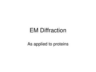
Detector System Pictures of the the diffraction patterns will be taking by using a micro channel plate (MCP) detector that basically works as an electron amplifier in which the incoming electrons generate secondary electrons. In this case, the incoming electrons enter channels in which they are accelerated by an electric field and generate the secondary electrons. The size of the channels is on the order of 12 μm, which is the highest attainable spatial resolution. There are four plates of which three are connected to high voltage supplies and one is grounded. The four plates are respectively at -1 kV, 0 V, +1 kV and +3 kV. The accelerated electrons hit a phosphorous screen in which photons are produced due to the electrons from the channels. This image is recorded by a CCD camera. Diffraction pattern from a gold foil at Pegasus Lab Ultrafast Electron Sources for Diffraction and Microscopy Workshop
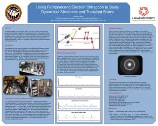
Complete System beam images at the screen Evolution of the beam size and the horizontal emittance are shown (from GPT). Emittance compensation is obtained after the solenoid (0.3μm from z=0.45m to z=1m). . Ultrafast Electron Sources for Diffraction and Microscopy Workshop
Synchronization Electron beam, laser and RF cavity synchronized by locking 80 MHz laser oscillator cavity with sub-harmonic of the RF frequency by commercial active phase lock loop. Ultrafast Electron Sources for Diffraction and Microscopy Workshop
NEG pump RF deflector Complete System (initial engineering) Solenoid CCD camera Photo-gun MCP Steering magnets Laser-sample Interaction chamber HV feed-through 3D model of the SUED system, from SolidWorks Tasks to be performed at UCLA Ultrafast Electron Sources for Diffraction and Microscopy Workshop
Conclusions • The SUED system will fabricated and tested at the Pegasus Laboratory at UCLA. The major components of the system are: • 100 kV photo-gun for 20 ps, 80 mA electron bunch generation; • Sample holder • RF deflector (20 kV voltage) for electron bunch streaking. Allowing ; • MCP detector • Synchronization System • Data acquisition/analysis system • We would love to hear feedback about what you like (or don’t like) about this system and anything we can do to improve it. You will hopefully be our customers! Ultrafast Electron Sources for Diffraction and Microscopy Workshop