Download
1 / 23
420 likes | 1.05k Views
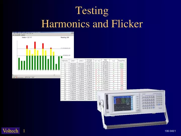
Testing Harmonics and Flicker. Harmonics & Flicker. Two different test standards: EN61000-3-2 & EN61000-3-3 EN 61000-3-2 controls the level of distortion of the current drawn by all equipment rated up to 16 amps.

E N D
Harmonics & Flicker Two different test standards: EN61000-3-2 & EN61000-3-3 • EN 61000-3-2 controls the level of distortion of the current drawn by all equipment rated up to 16 amps. • EN61000-3-3 controls the level of voltages changes that equipment rated up to 16 amps will impose on the ac supply. • Both standards have evolved over time • Harmonic standard. originally called IEC 555 Part 2 1987 • Flicker standard. originally called IEC 555 Part 3 1987 • Now referred to as EN61000-3-2 & EN61000-3-3 Standards • EN is short for Euro Norm; the version enforceable in law in European countries. The EN is usually identical to the IEC version.
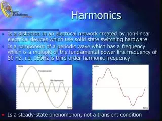
Current Harmonic Distortion Most modern power supplies draw current that is non-sinusoidal.
Current Harmonic Distortion The distorted current causes problems for electricity suppliers, consumers and product manufacturers. • The extra distorted current drawn does no useful work. The power factor is < 1, orV x A > WThis means more electricity must be generated, distributed and paid for than is consumed as useful energy. • The current distortion leads to to the phenomenon of triplen harmonic currents flowing in the neutral of three-phase systems – a fire risk in large office installations. • and to voltage distortion that can cause overheating in motors.
Current Harmonic Distortion Fourier analysis is used to describe any repetitive waveform in terms of sine-waves that are at multiples of the fundamental frequency. EN61000-3-2 controls current distortion by setting limits for the amplitude of the 1st 40 current harmonics. 50HZ 100HZ 150HZ
Requirements of EN61000-4-7 • How to measure to the harmonics is defined by EN61000-4-7 • It is a not a simple requirement. The following measurements must be made: • Power, Power Factor , Voltage Harmonics, Fundamental Current, POHC (Partial Odd Harmonic Current) as well as Current Harmonics. • And in a very specific way: NEW REQUIREMENTS • Measurements are made every 200mS, continuously without gaps.(10 cycles @ 50Hz, 12 cycles @ 60Hz). • Inter-harmonics must also be measured for current harmonics
Requirements of EN61000-4-7 • Harmonic measurements every 200mS - 400+ measurements! • Continuous no-gap analysis • All measurements filtered by 1.5s time-constant filter
Example Inter-harmonic group • 6th harmonic (300Hz @ 50Hz) 1/2 1/2
Applying Limits to Harmonics - EN61000-3-2 • The limits for pass and fail are set by product groups called Classes: • The limits are different for each harmonic and each of the 4 classes, A, B, C &D • Class Determination is :- • If device power is 75-600W and a PC , Monitor or TV then Class D • If handheld portable tool, then Class B • If Luminaries then Class C • If not Class B ,C, or D, or 3 phase then class A.
Applying Limits to Harmonics - EN61000-3-2 • Example Class C limits - calculated from AH01 and PF • Information from the PC Software ‘Help’ system
Applying Limits to Harmonics - EN61000-3-2 Limit 2 Limit 1
Applying Limits to Harmonics - EN61000-3-2 Maximum reading Vs Limit 2 Average reading Vs Limit 1 • Limits are set for the average of each harmonic during the test (L1) AND the maximum of each harmonic (L2).
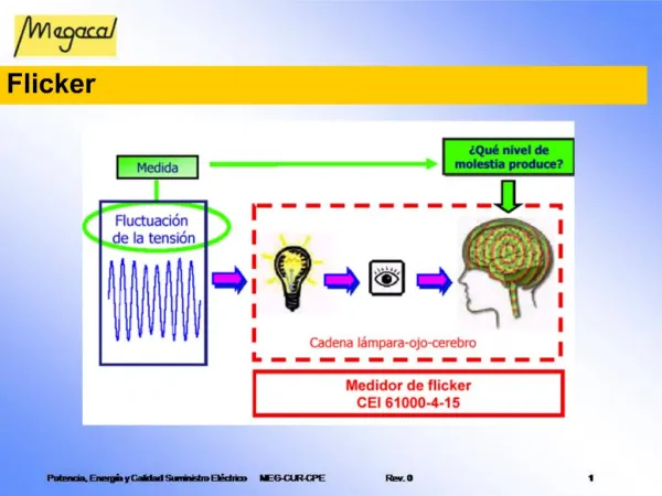
Flicker - Causes The AC supply cabling to a building will have a source impedance Any variation of loads will cause a voltage change at the distribution point This fluctuation of voltage will then make the lamps “Flicker”
Flicker –The Pst = 1 Curve • The Human tolerance to light flicker is mapped on the Pst = 1curve. • Any point on the curve has the same perceived level of annoyance • Pst = Perceptibility short term
EN61000-4-15 – The Flickermeter • For real-life random voltage changes, a flickermeter is used is used to duplicate the human perception of flicker. • A flickermeter measures rms voltage changes every half-cycle (10ms) and filters the measurements just like the lamp-eye-brain chain. • The filtered changes are classified to generate a table of the probability that a ‘class’ of voltage change will occur.
Measurement Equipment • The Harmonics and Flicker standards require fast and accurate analysis of electrical power quantities: • Continuous harmonics: • 400+ measurements every 200ms. • Discrete Fourier Transform for a reference instrument. • Continuous voltage changes: • every 10ms (1/2 cycle@50 Hz), • real-time flickermeter processing. • Limit checking and reports • Calculation of harmonic limits from averaged and maximum readings • Comparison to different class limits • Recording and presentation of results
The PM6000 • Up to 6 wattmeter channels • Accuracy: 0.02% of reading, 0.05% of range • Bandwidth: 10MHz • Sampling rate: 40 MSPS • Display: Bright color VGA • Connectivity: RS232, IEEE488, Printer, Ethernet • Connectivity (Future Release): PCMCIA for analog I/O including torque and speed, USB
PM6000 Measurement Channel • Built on 15+ years of Voltech analog know-how • Unrivalled accuracy and bandwidth combination • Layout and timing minimise phase delay for best Watts accuracy • A- D Convertor • 14-bit • 40MSPS Max • 5MSPS Min • PCI Bus • Continuous 5 MSPS data from every channel. • No analysis gaps, no missing data ±5V i DSP 200MHz v • Isolation • 4kVpk • CMRR: • 140dB @ 60Hz • 95dB @ 1MHz • Pulse Transformers • Data and control. • Provide superior CMRR than opto-isolators ±12V
References • Harmonic Limits • IEC 61000-3-2 -Consol.Ed.2.1 (2001) • All electrical and electronic equipment up to 16A. 220 to 240V 50 or 60Hz. • IEC 61000-3-12. • All electrical and electronic equipment rated 16A to 75A. 230/400V 50 or 60Hz. • Harmonic Measuring Equipment • IEC 61000-4-7 (2002)- 200ms window and Interharmonics requirement mandatory end 2007 • Flicker Limits • IEC 61000-3-3 -Consol.Ed.1.1 (2001) • All electrical and electronic equipment up to 16A. 220 to 250V line to neutral at 50Hz. • IEC 61000-3-11 Ed.1 (2000) • All electrical and electronic equipment 16A to 75A. 220 to 250V 50Hz. • Flickermeters • IEC 61000-4-15 Ed.1.1.(2003) • Help information • Voltech IEC61000 software for the PM6000. • Standards from: www.iec.ch • Software from: www.voltech.com (free download).
End of Presentation Thanks for listening!