Download
1 / 43
530 likes | 990 Views
Microwave Kinetic Inductance Detectors for X-ray Science. Antonino Miceli FNAL Research Techniques Seminar April 24, 2012. Outline. Why Superconducting Detectors? Detector Requirements Applications Overview of MKIDs MKID activities at Argonne MKID resonator readout . Acknowledgements.

E N D
Microwave Kinetic Inductance Detectors for X-ray Science Antonino Miceli FNAL Research Techniques Seminar April 24, 2012
Outline • Why Superconducting Detectors? • Detector Requirements • Applications • Overview of MKIDs • MKID activities at Argonne • MKID resonator readout
Acknowledgements • Tom Cecil (XSD Staff) • Orlando Quaranta (Post-doc) • Lisa Gades (XSD Staff) • Outside Collaborators: • Professor Ben Mazin (UCSB) • MSD/UChicago TES Team (Novosad et al) • CNM Cleanroom Staff
Superconductors Detectors for X-ray Detector R&D • Energy dispersive semiconductor detectors have almost reached their theoretical limits • e.g., Silicon Drift Diodes have energy resolution ~ 150 eV at 6 keV • Limited R&D on spectroscopic detectors • Only effort is Silicon array detector of Peter Siddons (BNL) and Chris Ryan (Australia) • Using silicon arrays to achieve large collection solid angles for fluorescence experiments. • Leverages local facilities and existing projects. • ANL’s Center for Nanoscale Materials for device fabrication • Many groups with thin film deposition experience • Superconducting Transition Edge Sensors for UChicago’sSPTpol • ANL’s Material Science Division
Detector Requirements • Solid angle coverage • Pixel area and sample-detector distance • Count-rate • Need lots of pixels (i.e. multiplexing) if you going to deal with superconducting detectors, which tend to be slow • Peak-to-background ratio • Maximize charge collection • Minimum of 1000:1 • Limits overall sensitivity • Energy resolution • Depends on applications (1-50eV at 6 keV)
Applications for superconducting x-ray detectors? • X-ray Inelastic Scattering • Access wide range of excitations. • Superconducting detectors allows broadband and efficient measurement compared to crystal analyzers (i.e., wavelength dispersive spectrographs). • X-ray Fluorescence • Fluorescence line overlap in complex biological samples • Fluorescence Tomography • Needs pixelated energy-dispersive detectors • White-Beam Diffraction (ED-XRD) • Versus angle-dispersive diffraction • Using monochromatic incoming beam and area detector • Complex sample environments(e.g., high-pressure cells)
Quasiparticle detectors • Use small Superconducting Energy Gap • Break Cooper Pairs • Use Cooper Pairs as detection mechanism (like electron hole pairs in a semiconductor) Semiconductor Energy Gap: ≈ 1 eV Superconductor Energy Gap: ≈ 1 meV Cooper Pair How to measure change in quasiparticle number?
Microwave Kinetic Inductance Detectors Observables…. • Quasiparticle generated by x-ray causes an inductance increase (i.e., “kinetic inductance”) • Measure inductance change in a LC resonating circuit DLs Multiplexing: Lithographically vary geometric inductance/resonant frequency… DRs • 1024 pixels demonstrated in 2011 • People are contemplating 10k pixels now • Limited by room temperature electronics
62eV Mazin et al 2006 What has been shown already for x-rays?
MKIDs @ Argonne for synchrotrons • The goal is moderate energy resolution (< 20eV) with good count rate capabilities (> 200kcps) (i.e., ~200-500 pixels) • Leverages Argonne’s micro/nano-fab facilities (CNM) and superconductivity expertise (MSD); Astronomical TES bolometer program(MSD & UChicago). • Three Main Aspects: • Device Fabrication • Fabrication is completely in-house • Relatively “simple”… patterning of metal (deposition, photolithography, etching) • Film quality is very important! • Initially aim a simple device, then progress to more complex designs (e.g., membrane-suspended) • Dedicated deposition system on order. • Cryogenics and Device Characterization • We are mostly limited by how fast we can test devices. • Readout electronics • Initially the analog readout for characterization. • Digital FPGA-based array readoutin the near future.
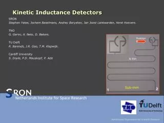
Anatomy of an MKID – Our work (one design) Inductor/Absorber 1 pixel 1 micron WSi2 (XSD) Capacitor 15 pixels 2 mm • First x-ray pulses at APS in January 2012! • Fe-55 and Cd-109
Detector Testing • Cryostat • Cryogen Free ADR • T = 100 mK for 2 days • 3-4 hour recycle time • Microwave Electronics • Vector Network Analyzer • IQ mixing • Control & Data Analysis Software Cryostat Microwave Electronics Be window (x-ray transparent)
Inside the cryostat… Attenuator 60 K stage m-metal shield NbTi (superconducting) coax 0.5K stage LNA Stainless Steel coax Sample box @ 60 mK 4 K stage
Measure the transmission through the device (S21) • Wide range of frequency: 0.3 - 20 GHz • Easily identify resonators: • Resonance frequencies, Quality Factors (Qr, Qc, Qi) • Cannot measure pulses nor noise VNA
IQ mixing (Pulses and Noise) • Homodyne mixing • Demodulate to 0 Hz (DC) and monitor for changes in Re(S21) and Im(S21) (i.e.,I & Q) • Amplitude = sqrt(I2+ Q2) • Phase= arctan(Q/I) Signal Generators IQ Mixer Variable attenuator IQ Mixer
IQ Fitting and parameter extraction Imag (S21) Real (S21) Frequency (GHz)
Pulses I &Q Time (ms) Amplitude Phase • Pulse fitting • Decay Time -> Quasiparticle life time • Phase pulse height -> Energy of the incident photon • The signal in phase is larger than amplitude
Tungsten Silicide MKIDs • We have been searching for dense materials for x-rays. • WSixis a material with low Tc, high kinetic inductance fraction and good quality factors. • Similar to Titanium Nitride • Maybe also be interesting for optical MKIDs. arXiv:1203.5064v1
Optical MKIDs (Mazin et al) -- Spectrophotometry • R=E/ΔE=16 at 254 nm • Limited by LNA/power handling/Q Mazin et al., Optics Express 2012
A readout for large arrays of Microwave Kinetic Inductance Detectors (McHugh, Mazin et al, arXiv:1203.5861v1) How to readout 1024 MKIDs….
Another technology – Transition Edge Sensors • TES have the best energy resolution (not Fano limited) • However, TES require relatively complex cryogenic electronics which makes multiplexing difficult. • Limited to 200 pixels right now. • Also, larger pixel means slower response….
TES are evolving towards MKID/resonator readout • “Microwave SQUIDs” • Eventually would like a wideband, quantum-limited LNA for MKIDs (i.e., don’t need SQUID anymore) • Josephson parametric amp (J. Gao et al) • arXiv:1008.0046v1 • Kinetic Inductance parametric amp (P. Day et al) • arXiv:1201.2392v1 B. Mates et al ApL 2008 (NIST) Superconducting microwave resonant circuits for the detection of photons from microwaves through gamma rays, Irwin, K.D., et al. Microwave Symposium Digest (MTT), 2011 IEEE MTT-S International , vol., no., pp.1-4, 5-10 June 2011
Conclusions • Superconducting detector development has started at the APS. • Testing infrastructure (cryo, electronics, analysis software) is complete. • Now focusing on device fabrication and iterating on designs • MKIDs are a path towards high count rates and higher solid angle coverage. • Has the potential to provide a very unique capability (detector/instrument) for the APS. • MKIDs are a relatively young technology and there is room for R&D. • Thank you!
Silicon Drift Diodes • Commercially available • E.g., Vortex 4-pixel SDD (4 x 40mm2) • Performance of single pixel SDDs (measured) • MnKa FWHM ~ 250 eV (Max Count rate ~ 250 kHz per pixel) • MnKa FWHM ~ 175 eV (Max Count rate ~ 100 kHz per pixel) • SDD have reached their limits of energy resolution. • Only improvement to be made is more pixels to increase total count rate throughput and solid angle collection. • Thus, the MAIA detector (BNL/Australia)!
Speed and resolution are inverse proportional. • Controllable thermal conductance to bath (“G”) • SiN membrane geometry
Phonon-Coupled MKIDs -- Single Photon Emission CT -- SPECT • SPECT Imaging (for animals) • Patrick La Riviere thinks phonon-coupled MKIDs might be good for this. • Also interesting for high-energy x-ray applications Sunil Golwala et al
Current Status of MKID Research at APS II Resonator • Exploring various detector configurations • Quasiparticle Trapping Tradition Configuration • 60eV resolution and 4000cps per pixel proven in 2006 • 30eV should be “easily” possible • More is understood about noise sources • 2eV is theoretical limit at 6keV • Lump-element design (WSix) No charge diffusion High Peak-to-Background • Phonon-Coupled Large pixels and thick silicon (or other dielectric material for absorption SiN membrane Silicon Absorber (1mm) Inductor/Absorber Capacitor
Pump-probe XAS w/o mono • 3eV at 7keV • 80Hz with 40 pixels (256 possible today) • 80Hz * 256 = 20kHz (TDM) • 80Hz * 1000 = 80kHz (CDM) This starts to be very interesting for RIXS/XES/XANES
MKIDs – Readout Scheme Multiplexing is main advantage of MKIDs over STJs and TES Should be able to readout ~4000 pixels
16-bit D/A 14-bit A/D FPGA-based IQ demodulation (Xilinx SX95T RF Engines Channel Core) IQ Mixer 16-bit D/A X X 14-bit A/D Low Pass Filters MKID Array readout • Room temperature electronics • Transfer complexity from cryogenic electronics (TES & SQUIDs) to room temperature. • Scalable system • Array size limitation is room temperature electronics (512 is practical today) • Riding on Moore’s Law for room temperature microwave integrated circuits developed for the wireless communications industry. GHz Synthsizer
Quasiparticle Generation – A Cascade Process Incoming Photon absorbed, ionizing atom and releasing inner-shell electron • First Stage: Rapid energy down-conversion (electron-electron interactions secondary ionization and cascade plasmon emission) • e.g. 10keV photoelectron down-conversion to a thermal population of electrons and holes at a characteristics energy ~ 1eV takes 0.1 ps (Kozorezov et al ) • 1st stage ends when electron-phonon inelastic scattering rate dominates electron-electron interactions. • Second Stage: ~ 1eV down-convert to large number of Debye energy phonons • Energy of phonon distribution exceeds energy of electron distribution • Debye energy of superconductors is larger than SC gap energy • Phonons with energy > 2 D will generate quasiparticles. Finally, we have a mixed distribution of quasiparticle and phonons: • Nqp ~ Ephoton/D • But scaled down because large percentage of photon energy stays in the phonon system • For Tantalaum, 60% energy resides in qp system. (Kurakado) (Efficiency h) • Nqp = hhn/D • At 6keV and Ta absorber, D = 0.67 meV 5 Million qp!!
Phonon Trapping • Dominant phonon loss mechanism for Ta and Al is through the substrate. • Copper Pair breaking phonons Mean Free path ~ 50nm • Effective quasiparticle lifetime is lengthened by phonon trapping. • Acoustic match between superconducting film and substrate. • Thus thicker films or membrane-suspended absorbers.
Two major classes of Superconducting Detectors • Thermal Detectors (i.e., Transition Edge Sensors) • Quasiparticle Detectors
Transition-Edge Sensors (TES) 1/e response time = 100 μs - 1 ms Kent Irwin, NIST
Transition-Edge Sensors (TES) • TES have the best energy resolution (not Fano limited) • However, TES require relatively complex cryogenic electronics which makes multiplexing difficult. • Limited to 200 pixels right now. • Also, larger pixel means slower response…. Irwin & Ullom, NIST
TES array at NSLS (NIST U7A) Commissioned at NSLS this year…. Waiting for results…
Gamma-Ray TES Array (NIST + Los Alamos) • Resolution • 25 eV at 100 keV for 1 mm2 • 20eV at 40keV for 1 mm2 • 70 eV at 100 keVfor 2 mm2 • Count Rate • 10Hz/pixel (now) • 25Hz/pixel (soon) • Pixels • 256 (now) • 1024 (soon)