Download
1 / 38
380 likes | 390 Views
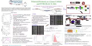
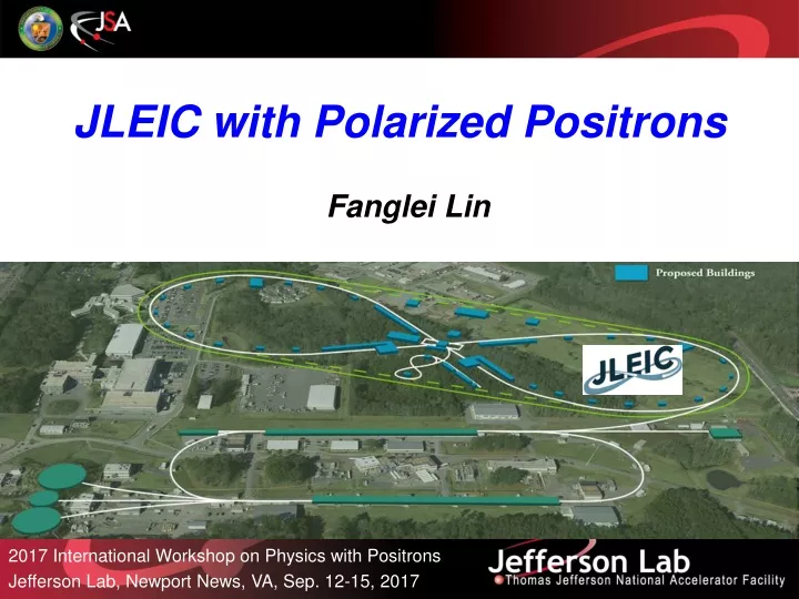
Fanglei Lin. JLEIC with Polarized Positrons. 2017 International Workshop on Physics with Positrons Jefferson Lab, Newport News, VA, Sep. 12-15, 2017.

E N D
Fanglei Lin JLEIC with Polarized Positrons 2017 International Workshop on Physics with Positrons Jefferson Lab, Newport News, VA, Sep. 12-15, 2017
S. Benson, A. Bogacz, P. Brindza, A. Camsonne, E. Daly, Ya.S. Derbenev, M. Diefenthaler, D. Douglas, R. Ent, Y. Furletova, D. Gaskell, R. Geng, J. Grames, J. Guo, F. Hanna, L. Harwood, T. Hiatt, Y. Huang, A. Hutton, K. Jordan, G. Kalicy, A. Kimber, G. Krafft, R. Li, F. Lin, F. Marhauser, R. McKewan, T. Michalski, V.S. Morozov, P. Nadel-Turonski, E. Nissen, H.K. Park, F. Pilat, M. Poelker, R. Rimmer, Y. Roblin, T. Satogata, M. Spata, R. Suleiman, A. Sy, C. Tennant, H. Wang, S. Wang, G.H. Wei, C. Weiss, R. Yoshida, H. Zhang, Y. Zhang - JLab, VA D.P. Barber - DESY, Germany Y. Cai, Y.M. Nosochkov, M. Sullivan - SLAC, CA S. Manikonda, B. Mustapha, U. Wienands - Argonne National Laboratory, IL S. Abeyratne, B. Erdelyi - Northern Illinois University, IL J. Delayen, C. Hyde, K. Park, S. De Silva, S. Sosa, B. Terzic - Old Dominion University, VA Z. Zhao - Duke University, NC A.M. Kondratenko, M. Kondratenko - Sci. & Tech. Laboratory Zaryad, Russia Yu. Filatov - Moscow Institute of Physics and Technology, Russia J. Gerity, T. Mann, P. McIntyre, N.J. Pogue, A. Sattarov - Texas A&M University, TX V. Dudnikov, R.P. Johnson - Muons, Inc., IL G.L. Sabbi - LBNL, CA J. Ellison, K. Heinemann - University of New Mexico, NM Z. Conway, D. Rubin, D. Sagan – Cornell University, NY JLEIC Collaboration
Outline • Overview of Jefferson Lab Electron Ion Collider (JLEIC) Design • Why EIC • Why EIC at Jlab • JLEIC design strategy and performance • JLEIC Key design features • JLEIC with polarized positron • Physics • Physics requirements • PEPPo based polarized positron injector • Scheme • Key aspects needed to be considered • Summary
Electron Ion Collider (EIC) Recommendations in NSAC LRP 2015: Continue existing projects: CEBAF, FRIB, RHIC. “…a U.S.-led ton-scale neutrinoless double beta decay experiment” “…a high-energy high-luminosity polarized EIC as the highest priority for new facility construction following the completion of FRIB” “…small-scale and mid-scale projects and initiatives that enable forefront research at universities and laboratories” EIC Community White Paper arXiv:1212.1701
Why EIC at Jefferson Lab • Large established user community in the field • CEBAF, the world highest energy SRF linac, as a full energy e- injector • A Green Field new ion complex and two new collider rings provide opportunity for a modern design for highest performance • Design meets experimental needs • Broad CM energy range • Wide range on ion species • Full acceptance detectors • High luminosity • High polarization • Low technical risk • Design largely based on conventional technologies
Electron complex CEBAF Collider ring Ion complex Ion source / Linac Booster Collider ring IP/detectors Optimum detector location for minimizing background Hori. Crab crossing Polarization Figure-8 shape rings Jefferson Lab Electron Ion Collider (JLEIC) 8-100(400) GeV 3-12 GeV 8 GeV 2015 2012 & SRF Linac arXiv: 1504.07961 arXiv: 1209.0757 May 17 update: https://eic.jlab.org/wiki/index.php/Main_Page
Strategy for High Performance • High Polarization • All JLEIC rings are in a figure-8 shape • critical advantages for both beams • Spin precessions in the left & right parts of the ring are exactly cancelled • Net spin precession (spin tune) is zero, thus energy independent • Spin can be controlled & stabilized by small solenoids or compact spin rotators • The only practical way for accelerating and storing polarized deuterons High Luminosity • Conventional approach for hadron colliders • Few colliding bunches low bunch freq. • High intensity long bunch and large β* • JLEIC based on high collision rate of short modest-charge low-emittance bunches • KEK-B reached > 2x1034/cm2/s Super-KEKB aims for ~ 1036/cm2/s Beam Design • High repetition rate • Low bunch charge • Short bunch length • Small emittance Damping • Synch. radiation • Electron cooling IR Design • Small β* • Crab crossing Full acceptance primary detector includingfar-forward acceptance
JLEIC Baseline e-p Parameters Similar high performance can be achieved for electron-ion (e-A) collisions
e-p Luminosity & Upgrade Potential Baseline Upgrade to 100 GeV CM energy Upgrade to 115 GeV CM energy (LHC SC magnet) Upgrade to 140 GeV CM energy Future energy upgrade options: new ion ring with higher dipole field • 6 T (Super-ferric): Proton energy up to 200 MeV CM energy up to ~100 GeV • 8.4 T (LHC): Proton energy up to 280 GeV CM energy up to ~115 GeV • 12 T (TBD): Proton energy up to 400 GeV CM energy up to ~140 GeV
JLEIC Achieved Design Goals Energy • Full coverage of CM energy from 15 to 65 GeV • Electrons 3-10 GeV, protons up to 100 GeV, ions up to 40 GeV/u Ion species • Polarized light ions: p, d, 3He, and possibly Li • Un-polarized light to heavy ions up to A above 200 (Au, Pb) Support 2 detectors • Full acceptance capability for the primary detector Luminosity • 1033 to 1034/cm2s per IP in a broad CM energy range, • Highest luminosity at CM energy around 45 GeV Polarization • At IP: longitudinal for both beams, transverse for ions only • All polarizations >70% Upgradable to higher CM energy/luminosity • 14 GeV electron, 400 GeV proton, and 160 GeV/u ion ~150 GeV CM Design performance is consistent with the EIC White Paper requirements
Electron Collider Ring Layout • Possible cost reduction by reusing PEP-II RF and vacuum pipe in the electron collider ring Spin rotator Spin rotator CCB Tune trombone & Straight FODOs R=155m e- 81.7 Arc, 261.7 Future 2nd IP RF RF Spin rotator Spin rotator IP Forward e- detection and polarimetry
Ion Collider Ring Layout disp. supp./ geom. match #3 disp. supp./ geom. match #2 norm.+ SRF Arc, 261.7 tune tromb.+ match elec. cool. R = 155.5 m 81.7 future 2nd IP Polarimeter det. elem. disp. supp. ions beam exp./ match IP disp. supp./ geom. match #3 disp. supp./ geom. match #1 • Protons: 100 GeV/u (63 GeV/u in COM with 10 GeV e) Lead: 40 GeV/u (40 GeV/u in COM with 10 GeV e) • Super-ferric magnets (cos under consideration as risk mitigation)
DC cooling for emittance reduction BBC (bunched beam cooling) for emittance preservation against intra-beam scattering Multi-Step Cooling Scheme ion sources DC cooler BB cooler ion linac Booster (0.285 to 8 GeV) collider ring (8 to 100 GeV) DC
High-Energy Bunched Electron Cooler • High-current magnetized electron beam maintains low ion beam emittances forhigh luminosity • SRF linac for acceleration and subsequent energy recovery for high energy efficiency • Circulator ring to relax requirements on the electron source and ERL
Figure-8 concept: Spin precession in one arc is exactly cancelled in the other Spin stabilization by small fields: ~3 Tm vs. < 400 Tm for deuterons at 100 GeV Criterion: induced spin rotation >> spin rotation due to orbit errors 3D spin rotator: combination of small rotations about different axes provides any polarization orientation at any point in the collider ring No effect on the orbit Polarized deuterons Frequent adiabatic spin flips Ion Polarization n = 0 Start-to-end Zgoubi simulation of proton acceleration Zgoubi simulation of proton spin flip
Electron Polarization • Universal spin rotator • is made of sequence of solenoid and dipole sections, • makes the spin longitudinal at IP, • has longitudinal spin matching, • ensures the same lifetimes for both polarization states. • Two highly polarized bunch trains maintained by the top-off injection. Polarization Configuration s=0.027 s=0.038 s=0.027 s=0.038 Spin tracking using ZGOUBI Spin tune scan using SLICKTRACK Synchrotron sideband spin resonances suppressed compared to a racetrack
Detector Region Concept Possible to get ~100% acceptance for the whole event Central Detector/Solenoid Scattered Electron Ion beamline Electron beamline Dipole Dipole Forward (Ion) Detector Particles Associated with struck parton Particles Associated with Initial Ion Courtesy of R. Yoshida
Interaction Region • Integrated detector region design developed satisfying the requirements of • Detection – Beam dynamics – Geometric match • GEANT4 detector model developed, simulations in progress IP e Compton polarimetry ions forward ion detection forward e detection dispersion suppressor/ geometric match spectrometers p (top view in GEANT4) e low-Q2 electron detection and Compton polarimeter Forward hadron spectrometer ZDC
Crab Crossing • Restore effective head-on collisions • Local compensation scheme with crab cavities upstream and downstream of IP • Cavities are placed at (n+1)/2 phase advance relative to IP with large x • Deflective crabbing • Demonstrated at KEK-B • Essential for high-luminosity LHC • Prototype developed at ODU Location of crab cavities π/2 3π/2 Outgoing At IP Incoming 35 cm 19 cm
JLEIC is an electron and ion collider Positron ?
Deeply Virtual Compton Scattering (DVCS) JLEIC provides high precision measurements of DVCS process, necessary to study GPD, beam charge and beam-spin asymmetry. Links to the imaginary part of the interference amplitude and express the important benefit of a polarized positron beam for GPD
Deep Inelastic Scattering (DIS) DIS w/ polarized ep beams parity violation in neutral current DIS DIS w/ unpolarized ep beams Neutral Current search for experimental evidence for right-handed charged-current weak interactions JLEIC Charged Current If not =0 => new physics !
Generation of Polarized Positrons Not compatible with continuous injection facilities Polarization is low High laser power High electron beam energy
Generation of Polarized Positrons (cont.) • Polarized Electrons for Polarized Positrons (PEPPo) Concept Polarized Bremsstrahlung Polarized Pair Creation E.G. Bessonov, A.A. Mikhailichenko, EPAC (1996) A.P. Potylitsin, NIM A398 (1997) 395 E.A. Kuraev, Y.M. Bystritskiy, M. Shatnev, E.Tomasi-Gustafsson, PRC 81 (2010) 055208 S1 D • PEPPo Experiment Pcirc(g) / Pz (e-) (PEPPo Collaboration) D. Abbott et al., Phys. Rev. Lett. 116 (2016) 214801 S2 Pz (e+) / Pcirc (g) Pe+ PT D Pe- e+ Calorimeter T2 e- T1 PEPPomeasured the longitudinal polarization transfer from 8.25 MeV/c e- to e+ in the 3.07-6.25 MeV/c momentum range. See L. Cardman’s talk Te+ / (Eg – 2me+) Eg/ Te-
PEPPo Based Positron Injector • PEPPo provides a new option to create polarized positrons with electron beam that has low energy in a 10-100 MeV range. • Pro: low neutron radiation • Con: low position yield (10-5to 10-3) • PEPPo + accumulation of • “hot” positrons after conversion: hard to accumulate with large phase space distribution • “cold” electrons before conversion: easy to accumulate with dense electrons • Design of the polarized positron injector should • reach averaged injected positron current (in a pulse mode) around or larger than 3nA in order to have reasonably short injection time and high equilibrium polarization, and • base on the state-of-the-art technology in each major step, or with modest R&D effort. Accumulation of polarized electrons Hitting the target to get positrons to CEBAF for JLEIC Polarized electron source
Polarized Positrons in JLEIC • The question always comes up “what about positron beams at an EIC” • Should give our accelerator colleagues some ROUGH idea about a reasonable lower threshold for • luminosity • polarization requirements for valuable since at an EIC • Bold proposal for valuable science with polarized positron beams: • Luminosity > 1033 • Polarization > 40% From Rolf Ent
Positron Injection Bunch Pattern • JLEIC polarized positron program requires • Injection of pulsed beams because a proper time is needed to allow the injected beam to damp to the design orbit in the electron collider ring • match of CEBAF and ring frequencies due to reuse of PEP-II RF system • 1/7 electron ring frequency matches 1/22 CEBAF SRF frequency because of fring/ fcebaf = 476.3MHz/1497MHz = 7/22 • injection of two polarization states 17 MHz bunch train, 60 bunches, 3.5 us Pol. e+ source 1-2 pC …… 60 s 20 to 85 ms 12 to 50 Hz, Iaveup to 6 nA
Positron Production Scheme Positron Conversion/Collection Efficiency ~ 10-5 - 10-3 60% in polarization Accumulator Ring (36m) 500-turn phase-space painting Bunch Management Polarized Electron 50 MeV Injector to CEBAF Harmonic kicker Extraction 50 MeV polarized e- 4 pC @ 748.5 MHz 50 MeV polarized e- 2 nC bunches @ 748.5 MHz ~30 MeV Polarized e+ 1pC@ 17 MHz 50 MeV polarized e- 2 nC @ 17 MHz Yield is chosen by assuming Δp=1MeV and 60% e- polarization transfer)
Key Aspects Needed to be Considered • High bunch charge and high repetition rate polarized electron source • QE decays quickly at high mA beam current • High bunch charge requires high voltage gun: increase risk of field emission or HV breakdown • Polarized electron accumulator ring • Beam dynamics during the multi-turn injection • Harmonic stripline RF kicker for the extraction • Spin dynamics • Polarized positron target and collection • High peak power but low average power at the target • Optimize IP2 figure of merit to improve collection efficiency • CEBAF magnet and diagnostics • Magnet polarity inversion, protection and calibration • Diagnostic system sensitivity
Polarized Electron Source • 4 mA is world record of polarized electron beam with 80 Coulomb (C) charge lifetime (R. Suleiman et al., PAC11, WEODS3) • Future polarized electron sources require 1000s C charge lifetime – possible improvements include: • Higher QE – new Distributed Bragg Reflector photocathode has 6.4% QE, world record • Improve gun vacuum to minimize ion bombardment • Larger laser size to distribute ion damage over larger photocathode area • Clean beam transport to maintain excellent vacuum – no halo or beam loss • Higher gun high voltage to reduce space-charge emittance growth, maintain small transverse beam profile and short bunch-length; clean beam transport See R. Suleiman’s talk
Accumulator Ring x Septum thickness + bunch width Accumulator ring x Injected beam See J. Guo’s talk • Accumulate electrons through multi-turn injection • CERN’s LEIR has a design of 75-turn injection of Pb54+ • We plan to push the injection number up to 500 turns in the accumulator ring • Extract the bunches with the proper frequency • Harmonic stripline kicker is considered to extract the bunched from a frequency of 748.5 MHz to 17 MHz • Maintain the polarization • Snake: the easiest way • Solenoid field integral: 0.1 Tm for 10 MeV, 0.5 Tm for 50 MeV, 1 Tm for 100 MeV • Figure-8: more bending, long ring circumference • Rotation: more machine elements • One spin rotator rotates the spin from longitudinal to vertical before the accumulator ring, another spin rotator rotate the spin from vertical to longitudinal after the accumulator ring.
High Power Target • Liquid Metal Target – lead-bismuth eutectic (LBE) • High Z = 82, 83 • Low melting point: 124 C • High boiling point: 1670 C • Multipole LBE targets tested on various accelerators • Natural circulation • Mechanical pumping • Electromagnetic pumping • Approaching 10 kW power level, CW Stainless Steel Windows (0.25mm) LBE (2mm) Output (e-,e+,γ) See C. Boulware’s talk Input (e-) “At that energy (100 MeV, 3.4 MW peak power, 0.6 kW average power) the amount of power deposited in the window would be a good deal smaller than at 10 MeV” ----- Chase Boulware
CEBAF Magnet and Diagnostics • Bipolar powered magnets need set point for a polarity inversion only • Quadrupoles and correctors • Given availability of tune-up diagnostics, none of the bipolar magnets have any known problems with polarity inversion. • Unipolar powered magnets need to swap the leads on the “shunt” controls attached to the magnet string being inverted, also need to swap power leads at the power supply • Dipoles: recirculation arc dipoles and spreader/recombiner vertical dipoles • The concerns are magnet over-temperature sensors, ground fault detection and power supply internal protections. But they are all independent of polarity inversion. The inversion of magnets only requires exchange the power leads at the supply output terminals. • Diagnostics • All diagnostic systems should work for a positron beam with a pulse current of a few tens of uA and peak power of 0.6kW. See M. Tiefenback’s talk
Summary • JLEIC design • meets physics requirements of high luminosity, high polarization and full acceptance detection, • bases on the state-of-the-art technology, with minimal R&D efforts, and • provides an opportunity of collision of polarized positrons (in addition to electrons) and ions, driven by a rich science interest. • Design of a dedicated PEPPo based polarized positron injector for JLEIC has been initiated to provide required polarized positron beams, considering • adequate luminosity and polarization for physics experiments • modest technical challenges in accelerator design
Acknowledgement • Thanks to Rolf Ent for his inspiration and support of exploration of polarized positrons in JLEIC. • Thanks to Yulia Furletova, Wally Melnitchouk, Farida Selim, Eric Voutier for their support in proving material of physics impact and benefits of positrons. • Thanks to Joe Grames, Jiquan Guo, Vasiliy Morozov, Yuhong Zhang for their enthusiastic discussion and brainstorming in the detail of machine design. Thank You for Your Attention !
High Polarization Photocathode R&D • 6.4% QE & 84% polarization at 776 nm from strained GaAs/GaAsP superlattice photocathode with GaAsP/AlAsP Distributed Bragg Reflector(DBR) • The highest QE & FOM of any reported high polarization photocathode • Possible to improve both QE & Pol • SBIR partnership Photo-cathode DBR Substrate Paper for SPIN and APL submission: W. Liu, S. Zhang, M. Stutzman, M. Poelker, Y. Chen, W. Lu, and A. Moy