Download
1 / 1
10 likes | 98 Views
Polarized Positrons at Jefferson Lab Jonathan Dumas ( JLab /LPSC ), Joe Grames ( JLab ), Eric V outier (LPSC). Outlook. The Experiment. We investigate the idea of generating polarized positrons using the CEBAF polarized electron photoinjector . - low energy (e - beam energy ≤ 8.5 MeV )

E N D
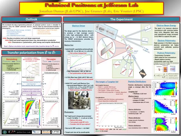
Polarized Positrons at Jefferson Lab Jonathan Dumas (JLab/LPSC), Joe Grames (JLab), Eric Voutier(LPSC) Outlook The Experiment We investigate the idea of generating polarized positrons using the CEBAF polarized electron photoinjector. - low energy (e- beam energy ≤ 8.5 MeV) - bremsstrahlung photons - low radiation level - thin LOW/HIGH power target A polarized positron source is intended for the ILC. E166 has demonstrated feasibility of a polarized positron source by pair creation: - high energy e- beam (≈50 GeV) - synchrotron photons - thin low power target Electron Beam Energy Electron Driver The goal is to measure electron momentum with precision better than 0.5%. Magnetic field map and operational range increased to 8.5 MeV to support this goal. • The design goal for the electron driver is to produce a high average current (1 mA), high polarization (85%) with energy up to ~ 10 MeV electron beam. The CEBAF photoinjector provides the necessary characteristics: • Electron Gun • GaAs/GaAsPsuperlattice photocathode • High QE ~1% at 780 nm (~6 mA/mW) • Test surface charge limit • High Polarization ~85% at 780 nm • => Test polarization at high current • 1.5 GHz fiber laser (500 mW @ 780 nm) • Test new 1.5GHz rf control module • 100kV DC Load Lock Electron Gun • demonstrated lifetime >250 C at 1 mA • (J. Grames et al., in Proc. of the 2007 Particle Accelerator Conference, THPMS064, p. 3130.) • => Field emission is limiting lifetime • Photoinjector • “G0” high bunch charge demonstrated • 1.3 pC @ 31 MHz ~2 mA at 1.5 GHz • Restore G0 setup • Test pulsed mode DF~0.1% • Consider 200 kV gun option? • Normal & SRF cavities => ~8.5 MeV • Target spot size set by quadrupoles 2008: Develop simulation tools and design experiment 2009: Build and install experiment beam line, demonstrate e+ production 2010: Characterize e+ (polarization, yield, energy and angular distributions) Goal = Deliver simulation tools, experimental data, baseline design for e+ source Electron Polarimetry High precision (~1%) Mott measures electron polarization (at higher current) and calibrates positron polarimeter. Transfer polarization from e- to e+ Positron Polarimetry • - Transmission Compton • - Well suited for low momentum • - Rapid relative monitor • Successfully used, e.g., E166 • (P.Schuler et al., in Proc. of the 17th international spin physics symposium, p. 1095.) In a material, e- radiate gs (Bremsstrahlung). gs (>1.022MeV) can create a e+/e- pair. Bremsstrahlung e- longitudinal g circular Pair creation g circular e+ longitudinal Polarization transfer depends on: -e- energy Ee- -g energy Eg -Target atomic number: Z -g scattering angle Polarization transfer depends on: - g energy Eg -e+ energy Ee+ -Target atomic number: Z -e+ scattering angle Electromagnetic shower : -Bremsstrahlung - Pair creation Particle Distributions Particle distributions (scattering angle vs energy) after the foil for: Tungsten foil: - Thickness: 0.25 mm Electron beam: - 1 bunch (0.67 pC-1 mA at 1.5 GHz) - energy of 5 MeV - transverse size of 1 mm The target: a Tungsten foil Polarization transfer calculation for both interactions. Olsen & Maximon, Phys. Rev. 114 (1957) • Use tungsten because: • High Z => greater EM shower • Low power target => Low cost • Thin target => better beam quality • Good thermal properties => extends deposited power limit • Considerations: • Positron yield (foil thickness optimization) • Power deposition (melting foil) Geant4 simulation: polarization distribution at the creation vertex Ee-= 5 MeV e- longitudinal = 100% Z=74 (Tungsten) g scattering angle=all Eg= 5 MeV g circular= 100% Z=74 (Tungsten) e+ scattering angle=all at the exitof the foil Electron distribution e- momentum ~ 4.7 MeV/c Scattering angle < 30o Photon distribution Large amount of photons Low energy Positron distribution Low momentum (0.5->2 MeV/c) ~58% at 2 MeV Eg= 5 MeV g circular= 100% Z=74 (Tungsten) e+ scattering angle=all Target thickness=0.25mm Ee-= 5 MeV e- longitudinal = 100% Z=74 (Tungsten) scattering angle=all Target thickness=0.25mm Ee-= 5 MeV e- longitudinal = 85% Z=74 (Tungsten) e+ scattering angle=all Target thickness=0.25mm Fig.7: Positron yield after the foil and power deposit in the target.