Download
1 / 43
440 likes | 609 Views
Business Analysis & Data Design ITEC-630 Fall 2008. Interface Design, Use Case Scenarios, Test Cases & Project Issues Professor J. Alberto Espinosa. Objectives. Discuss interface design issues Discuss instance scenarios Discuss test cases Briefly discuss non-functional requirements

E N D
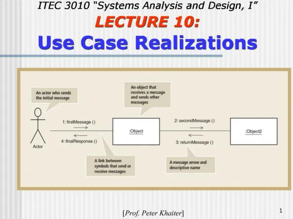
Business Analysis & Data DesignITEC-630 Fall 2008 Interface Design,Use Case Scenarios,Test Cases& Project Issues Professor J. Alberto Espinosa
Objectives • Discuss interface design issues • Discuss instance scenarios • Discuss test cases • Briefly discuss non-functional requirements • Discuss project issues
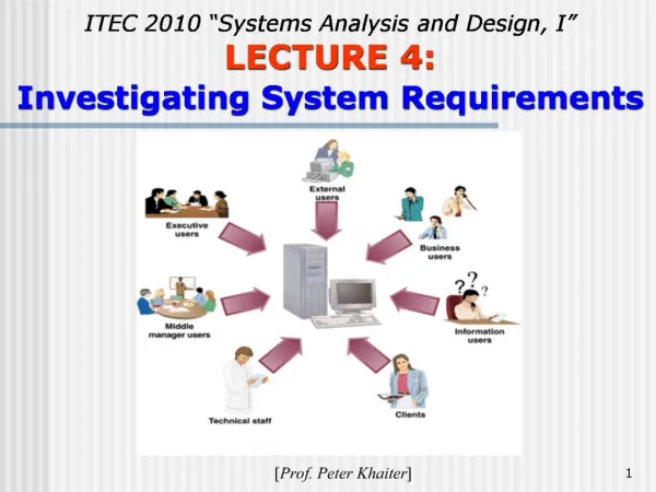
A Definition Interface:“The place at which independent and often unrelated systems meet and act on or communicate with each other”– Webster dictionary Network Hardware System User Software Software
If the actor is a user: • The interface captures how the user interacts with the system If the actor is a system: • The interface will contain the program commands our system needs to interact with that external system
Each Interface Has: • A name • A set of “operation signatures” indicating: • which data to “get” from the actor with the operation (i.e., Get UserId, Name, etc.) • Which data to “return” to the actor when the operation is complete • A storyboard (for user interface only): visual illustration of the sequence of screen designs to complete these operations
Example of Operation Signatures: Funds Withdrawal Interface • Get data from card magnetic tapeGet pass code from customer • Get customer transaction selection(user selects withdrawal) • Get account type for withdrawal • Get amount to withdraw • Return cash, or • Return error message to customer • Return thank you message to customer
A User Interface Can Be For: • Input into the system by the user for data entry or to query information from the system • A display output (on screen or other output device) by the system to the user • A printed output (on a printer or other output device)
Diagramming the Interface: with “Storyboards” • User interfaces can be diagrammed as “storyboards” • A storyboard is a series of drawings that depict how the system looks at the start of the operation and after each significant change to the look of the interface • Is like a sequence of screenshots that follows the use case execution sequence
Organization of a Storyboard Storyboard Sequence
What to Include in an Interface Design Specification • A list of all the interfaces between actors and use cases • For each interface (any actor – user or external system): • Indicate whether the actor is a user (human actor) or an external system • Prepare a list of operation signatures detailing all the data that is passed to/from the system before each operation and the data that is returned from/to the system after each operation • For users (human actors only): • Indicate when/if operations are taking place for data input, display outputs or printed outputs • Prepare a storyboard for all screen input/output displays and printouts • Design the visual interface for all screen input/output displays and printouts • For external system actors (only): • Indicate when/if operations are taking place to inputor output data from/to the system
General Quality Attributes of a User Interface Design • Ease of use • Intuitive use and navigation • Consistency across screens • Simplicity – e.g., no clutter, no information overload, no busy graphics • Exit/cancel options for users • Forgiving • Businesslike appearance • Readable and good color contrast • Reference sites:Cornell Univ: http://ergo.human.cornell.edu/ahtutorials/interface.htmlVirginia Tech: http://www.edtech.vt.edu/edtech/id/interface/Carnegie Mellon:http://www.usernomics.com/user-interface-design.html
Instance Scenarios • Are examples (i.e., paper prototypes) of how a Use Case will execute in a given situation • Per UML 1.3: “performance of a Use Case, initiated by a message instance by an instance of an actor” • They may represent a path (sunny day or rainy day) in the Use Case Flow of Events • Or specific instance within one of these paths • Experienced analysts prefer to keep Use Cases simple with low level of detail, so that they are easy to understand. • And complement them with instance scenarios that can help explore and gain more detailed insights into the Use Cases • They are particularly useful in modeling exceptions • Best candidates for instances: extreme values, exception conditions, and borderline conditions
Instance Scenarios UC 101-Ia Input Parameters Output Parameters Conditions UC 101 UC 101-Ib Input Parameters Use Case InstanceScenarios Output Parameters Conditions UC 101-Ic Input Parameters Output Parameters Conditions
Testing Test cases are useful for Ensuring that the system performs as required Test types: • UNIT TESTING:Ensure that each part of the system work well individually • SYSTEM TESTING:Ensure that all the parts work well together • REGRESSION TESTING: Ensure that new software work well with the existing software • ACCEPTANCE TESTING: By users and/or clients Methods: • BLACK BOX TESTING: Testing if the system does what is supposed to, without inspecting the internals of the system • CLEAR BOX TESTING: Inspecting and testing the internals of the system (opening the black box)
Test Cases • Each Use Case should have a “test suite” associated with it • Each test case in the suite represent a path in the Use Case Flow of Events • Ideally, each path should have a test case (difficult with large complex systems) • Pay attention to borderline conditions(e.g., customer withdraws maximum allowable cash, customer withdraws all funds available), which is usually where software fails
Path 4 Test SuiteExample:Withdraw CashUse Case Path 5 S Path 1 A Path 2 E Path 3 E SE S S SE A E A SE SE S E S SE A =Input or other action from an Actor S = An action performed by the system E = An exception (e.g., conditional flow) S
Test Cases UC 101- Path 1 Pre-conditions Post-conditions UC 101 UC 101- Path 2 Pre-conditions Use Case Test Suite Post-conditions UC 101- Path 3 Pre-conditions Post-conditions
Documentation • Use cases map directly to events that users will be engaged in • And to events in which external systems will interact with the system • So Use Cases can be used as the base to provide documentation for users • And for the interface with external systems • These documentation can be written to mirror Use Case, but perhaps with more user-friendly language, or • In the case of external system interfaces, with more technical language that relates to that system (e.g., TCP/IP connection, accounting system, etc.)
The Project Plan • It is based on iterations, per the UP • Define the iteration length • Develop a domain model early • Analyze, design, build, integrate, and test often • Estimate how many (fixed-length) iterations you will need for construction • Decide the order in which things will be built based on Use Case priorities • Try to build the core functionality of the product early (or at least prototype it)
Estimating Project Effort • Estimate the number of lines of code (LOCs) • Difficult to estimate upfront • Depends on the software language used • Not great for object-oriented systems & CASE tools • Constructive Cost Model (COCOMO) • A popular method • Effort estimation based on LOCs estimated • Same difficulties as with LOCs estimation • Use Case Points (UCP) • Similar to function points, but based on Use Case metrics • Function Points (FP) • Estimating effort based on what the software does, not LOCs • Every software function (e.g., a display, report, a data store) has a function count • Then adjusted to function points based on complexity factors
Use Case Points (UCP) (Rational Software – a new way of estimating effort) • Count Actors and multiply by their weight: • 1 for a simple actor (an external system with a well defined interface) • 2 for an average actor (an external systems with less defined interface or a person using a simple interface) • 3 for a complex actor (people using a more complex graphical interface) • Count Use Cases and multiply by their weight • 5 for simple Use Cases (3 transactions or less) • 10 for average Use Cases (4-7 transactions) • 15 for complex (more than 7 transactions) • A transaction is a set of Use Case steps performed entirely or not at all (i.e., number of paths) • Unadjusted Use Case Points (UUCP) • Adjust for complexity and environmental factors
FYI Only: Function Points (FP) • The traditional way of estimating effort • Count: • Number of user inputs • Number of user outputs • Number of user inquiries • Number of files • Number of external interfaces • Function Count = weight these counts based on their complexity and add them up • Function Points (FP) = adjust for other complexity factors