Download
1 / 13
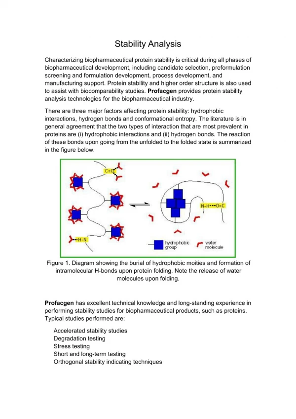
130 likes | 308 Views
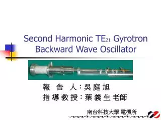
Stability analysis of a gyrotron backward-wave oscillation with an external injection signal. Student : Jhih Liang Shiao Advisor : Yi Sheng Yeh. [ NTHU ]. Outline. I. Introduction

E N D
Stability analysis of a gyrotron backward-wave oscillation with an external injection signal Student: Jhih Liang Shiao Advisor: Yi Sheng Yeh [ NTHU ]
Outline I. Introduction II. Stability analysis of a gyrotron backward- wave oscillation with an external injection signal III. Summary IV. References [ NTHU ]
Applications of Millimeter Wave • *朱國瑞、張存續、陳仕宏 “電子迴旋脈射 - 原理及應用 ”物理雙月刊(廿八卷二期)2006年4月
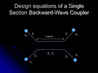
gyromonotron waveguide cavity modes forward wave interaction gyroklystron forward wave interaction gyro-TWT gyro-BWO backward wave interaction Types of Gyrotron Tubes • Four types of gyrotron tubes: (1) Gyromonotron High power oscillator (2) Gyroklystron High power amplifier (3) Gyro-TWT Broad bandwidth amplifier (4) Gyro-BWO Oscillator (frequency tuning)
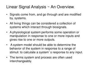
input wave electron beam output wave rc rw Basic Mechanism of Gyro-TWA • ※Δω=ω-Ωc≧0 • where Ωc = eB0/γm, γ=(1-v2/c2)-1/2 • ※Electron #1 initially gaining energy • →γ increases →Δω increases • →out of synchronism • →weaker interaction • ※Electron #2 initially losing energy • →γ decreases →Δω decreases • →approaching synchronism • →strong interaction [ UCD ]
R Time = 0.0, Efficiency = 0.0 % Time = 8.0, Efficiency = 8.2 % Time = 4.0, Efficiency = -5.0 % Time = 12.0, Efficiency = 26.8 % Cycltron Resonance Maser Interaction Mechanism *V. L. Granatstein, and I. Alexeff, High-power Microwave Source, Artech House, 1985.
100 1 3 8 = G k B . 0 80 ) z 60 H G ( 40 s f = 1 T E 1 1 20 0 -4 -2 0 2 4 k ( c m ) - 1 z Stability Analysis of an Injection-Locking Gyro-BWO Fig. (a) Profile of the interaction structure . (b) Magnetic field . (c) Normalized field profile versus z in a gyro-BWO. The oscillation frequency on free-running operation is 32.8525 GHz in the gyro-BWO. Parameters are Vb=100 kV, B0 =13.8 kG, Ib=5 A, α=1.1, and rc=0.09 cm. *Y. S. Yeh, T. H. Chang, and Y. C. Yu, “Stability analysis of a gyrotron backward-wave oscillation with an external injection signal,” IEEE. Trams. Plasma Sci., vol. 34, no. 4, 2006.
31.44 Steady-state solution 21.96 where 4.14 Stablesolution , -15.5° -180 ° -186° 0.05 1.5 7.5 ] = 32.84987 GHz [ Stability Analysis of an Injection-Locking Gyro-BWO
Fields of the circularly polarized TEmn mode Relativistic equation of motion waveguide Numerical Method and Simulation Model Boundary conditions (injection-locking regime) Field equation Boundary conditions (free-running regime)
Stability Analysis of an Injection-Locking Gyro-BWO Adler Curve B0=13.8 kG Pin=4 kW Pin=5.1 kW
Stability Analysis of an Injection-Locking Gyro-BWO 14.2 13.9 13.78
Summary • This study presents that the perturbation of a stable solution must decay in time to determine the stability of a steady-state solution, and the phase difference of the stable solution is restricted in the range between -90 ° and 90° • The simulated locking bandwidth curve is slightly asymmetrical at frequencies below the oscillation frequency, the reason may be that the field concentrates toward the upstream end at frequencies below the oscillation frequency, and show that the locking bandwidth curve is about 28 MHz at a relative power ratio of -20 dB. • The simulation result of the peak efficiency on the injection-locking operation increases to 34% at the magnetic field of 13.78 kG whereas the efficiency on the free-running operation is 30% at a magnetic field of 13.9 kG.
References [1] 物理雙週刊 p.426~433 (2006.4) [2] G. S. Nusinovich and O. Dumbrajs, IEEE Trans. Plasma Sci. 24, 620 (1996). [3] V. K. Yulpatov, Radiophys. Quantum Electron. 10, 471 (1967). [4] V. L. Granatstein, and I. Alexeff, High-power Microwave Source, Artech House, 1985. [5] R. A. York and T. Itoh, “Injection- and phase-locking techniques for beam control,” IEEE Trans. Microw. Theory Tech., vol. 46, no. 11, pp. 1920–1929, Nov. 1998. [6] Y. S. Yeh, T. H. Chang, and Y. C. Yu, “Stability analysis of a gyrotron backward-wave oscillation with an external injection signal,” IEEE. Trams. Plasma Sci., vol. 34, no. 4, pp.1523-1528 , Aug. 2006. [7]羅智陽, “A Gyrotron Backward-Wave Oscillator Driven by an External Signal” [8]廖志偉, “A Gyrotron Backward-Wave Oscillator Driven by an External Signal”