Download
1 / 34
340 likes | 540 Views
Amr Aldaiel - Andrew Kravitz Katie Noble - Zack Taylor - Alan Yim. Objectives. Wireless real-time video with illumination capabilities Remote manual operation via computer-based user interface Temperature sensor Control via keypad and LCD display. Preliminary Goals.

E N D
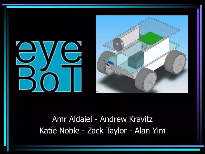
Amr Aldaiel - Andrew Kravitz Katie Noble - Zack Taylor - Alan Yim
Objectives • Wireless real-time video with illumination capabilities • Remote manual operation via computer-based user interface • Temperature sensor • Control via keypad and LCD display Preliminary Goals • Wireless network control • Automatic patrol mode • Smoke detector, CO detector Auxiliary Goals
Status • Basic chassis assembly complete • Preliminary power system schematics complete • Basic user interface implemented • PWM output from PIC • Preliminary FPGA and peripherals schematics
Rover Chassis • Made of 1/8” 5052 Aluminum Alloy • High strength-to-weight ratio • Excellent corrosion resistance • Good forming characteristics
Motor Selection • ReliaPro DC Reversible Gearhead Motor • Operating Range: 4.5V-12V • Speed at 12V: 35 RPM • 100:1 Gear Ratio • 2370 g-cm torque
Power Source • Werker Non-spillable Battery • 12V • 7.5 Amp Hours
Power Distribution System Tasks: • Design and build a Power Management Unit (PMU) • Build switching power converters as needed for different parts of the eyeBot • Ensure power is adequately distributed and efficiently managed
PMU Components • 1st Stage Step-Down Conversion • 2nd Stage Voltage Regulation (5V and 3.3V) • Optocoupling of Incoming PWM Signals • H-bridge Inverters for Motor Driving
Lighting • High intensity LEDs for area illumination, mounted on camera • OPTEK Inc. OVLEW1CB9 (White) • PIC will control a switch to turn LEDs on and off
Camera • Linksys WVC54GC • Capture Resolution • 320 x 240 • Interface Type • IEEE 802.11b/g • Ethernet 10Base- T/100Base-TX • Approximately ½ second delay at 20 FPS
User Interface - Concept • Programmed using Visual Basic • Will run independently on a PC • Send and receive information and commands through RS-232
Microcontroller • PIC18F8722 Microcontroller (80 Pin) • ECCP1/2 – Left/Right Motor PWM • ECCP3 – Camera Servo Control • Programmed Using MPLAB IDE & Microchip ICD2 • Allows stepping/breakpoints for code running on 18F8722 • Communications • RS-232 through MAX3232CDR RS-232 Driver • Serial Communication • FPGA through 10 Bit Parallel Bus • General I/O Pins for Thermometer, and LED Array Control • Operation at 10 MHz
Function: pwminit() void pwminit(void) { PR2=0x18; // Sets the Period Register for Timer 2 (100 KHz) TRISC=0; // Sets Port C to Output TRISG=0; // Sets Port G to Output TMR2=1; // Timer 2 Prescaler set to 1 for 100KHz operation T2CON=0b00000100; // Timer 2 Control Reg,Turns Timer 2 On CCP1CON=0b00101101; // Initialize CCP1 (Turn on PWM +2%) CCP2CON=0b00101101; // Initialize CCP2 CCP3CON=0b00101101; // Initialize CCP3 CCPR1L=26/4; //Sets CCP 1 to 26% Duty Cycle CCPR2L=50/4; //Sets CCP 2 to 50% Duty Cycle CCPR3L=74/4; //Sets CCP 3 to 74% Duty Cycle // ALL CCP duty cycles can be controlled to duty%= 4*CCPRxL+2% // Allows for 25 Speeds for the motors (12 Forward, 12 Back) // Servo can be controlled to 25 positions }
HPC-Explorer Board • Cheap Effective PCB • Built in wire-wrap/solder points for all general I/O Pins • Can Easily Build Ribbon Cable Interface for FPGA Bus • Built In Voltage Regulator for VDD and Ground of 18F8722 through 9-15V input • ICD 2 Jumper and RS-232 Com port on board. • Built in Temperature Sensor • 8 LED’s through Port D, for data checking • Easily Add on additional components
FPGA Overview • Xilinx XCS10 with XC18V256 EPROM • Interfaces between PIC, Keypad, LCD display, and any future peripherals • Handles chip selection based on three address bits • Communicates with PIC through 10 bit parallel bus
LCD • Will display: • temperature • direction • eyeBOT status • 20x4 character display • Considering: • HD44780 parallel interface • HD44780U driver
4x4 Keypad • Used for on-board eyeBOT control • Row/Column matrix will be encoded into 4 data bits by MM74C922 • MM74C922 also offers an interrupt signal and a keypad available signal
Feedback System • Optical encoders mounted on eyeBOT wheels • Quadrature decoders (HCTL2016) will send data through PIC and straight back to User Interface • Two possible encoder setups • Panel Mount • Code Wheel HEDS 5700 series HEDB-9000 series
Parts List • ReliaPro DC reversible gear-head motor • Werker 12V 7.5 amp-hour battery • Linksys WVC54GC • PIC18F8722 microcontroller • HPC-Explorer board • Xilinx XCS10 • XC18V256 EPROM • 20x4 character display • MM74C922 encoder
Division of Tasks • Amr • Power distribution system • Andrew • Microcontroller • Katie • FPGA, LCD/Keypad, motor feedback, peripherals • Zack • User interface, communication link • Alan • Rover assembly & mechanics, motors, FPGA, LCD/Keypad
Milestone 1 Deliverables • Preliminary Verilog code • Serial communication between GUI and PIC • Power distribution system complete for main components • Chassis complete with mounted camera and multiple levels Plexiglas • Streaming video in GUI
Milestone 2 Deliverables • All Primary Goals Accomplished • Wireless real-time video with illumination capabilities via computer-based user interface, keypad, and LCD display • Temperature sensor • Completely battery powered
Expo Deliverables • As many add-ons as possible • Automatic patrol mode • Wireless network control • Additional peripherals • Smoke detector • CO detector