Download
1 / 1
10 likes | 133 Views
Measuring Structural Motion Caused by a Simulated Earthquake using Smart Phone Accelerometer Technology Baron J. Richardson. Methods : Mathematically model the structural frequency using. Using the following formula: 2 π = (Hz) f=frequency in Hz ω =frequency in rad/s k=stiffness

E N D
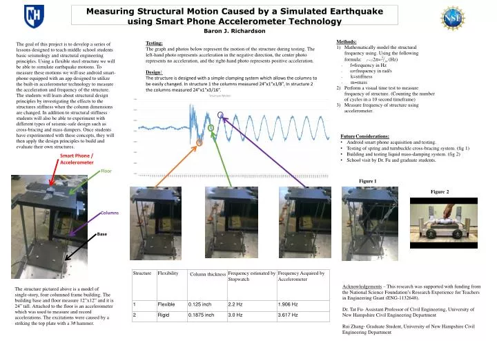
Measuring Structural Motion Caused by a Simulated Earthquake using Smart Phone Accelerometer Technology Baron J. Richardson Methods: • Mathematically model the structural frequency using. Using the following formula: 2π= (Hz) • f=frequency in Hz • ω=frequency in rad/s • k=stiffness • m=mass • Perform a visual time test to measure frequency of structure. (Counting the number of cycles in a 10 second timeframe) • Measure frequency of structure using accelerometer. Testing: The graph and photos below represent the motion of the structure during testing. The left-hand photo represents acceleration in the negative direction, the center photo represents no acceleration, and the right-hand photo represents positive acceleration. The goal of this project is to develop a series of lessons designed to teach middle school students basic seismology and structural engineering principles. Using a flexible steel structure we will be able to simulate earthquake motions. To measure these motions we will use android smart-phone equipped with an app designed to utilize the built-in accelerometer technology to measure the acceleration and frequency of the structure. The students will learn about structural design principles by investigating the effects to the structures stiffness when the column dimensions are changed. In addition to structural stiffness students will also be able to experiment with different types of seismic-safe design such as cross-bracing and mass dampers. Once students have experimented with these concepts, they will then apply the design principles to build and evaluate their own structures. Design: The structure is designed with a simple clamping system which allows the columns to be easily changed. In structure 1 the columns measured 24”x1”x1/8”, In structure 2 the columns measured 24”x1”x3/16”. FutureConsiderations: • Android smart phone acquisition and testing. • Testing of spring and turnbuckle cross-bracing system. (fig 1) • Building and testing liquid mass-damping system. (fig 2) • School visit by Dr. Fu and graduate students. Smart Phone / Accelerometer Floor Figure1 Figure 2 Columns Base Acknowledgements – This research was supported with funding from the National Science Foundation’s Research Experience for Teachers in Engineering Grant (ENG-1132648). Dr. Tat Fu- AssistantProfessor of Civil Engineering, University of New Hampshire Civil Engineering Department Rui Zhang- Graduate Student, University of New Hampshire Civil Engineering Department The structure pictured above is a model of single-story, four columned frame building. The building base and floor measure 12”x12” and it is 24” tall. Attached to the floor is an accelerometer which was used to measure and record accelerations. The excitations were caused by a striking the top plate with a 3# hammer.