Download
1 / 99
1.12k likes | 1.43k Views
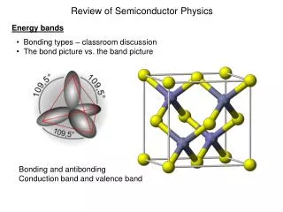
Lecture 03 Semiconductor Physics. Prepared By Dr. Eng. Sherif Hekal Assistant Professor, CCE department. ILOS. In this section, we will learn: The basic properties of semiconductors and, in particular, silicone – the material used to make most modern electronic circuits.

E N D
Lecture 03 Semiconductor Physics Prepared By Dr. Eng. Sherif Hekal Assistant Professor, CCE department Lecture 03
ILOS • In this section, we will learn: • The basic properties of semiconductors and, in particular, silicone – the material used to make most modern electronic circuits. • How doping a pure silicon crystal dramatically changes electrical conductivity – the fundamental idea in underlying the use of semiconductors in the implementation of electronic devices. • The two mechanisms by which current flows in semiconductors – drift and diffusion charge carriers. • The structure and operation of the pn junction – a basic semiconductor structure that implements the diode and plays a dominant role in semiconductors. Lecture 03
Agenda • Current Flow in Semiconductors • The pn Junction with Open-Circuit Terminals (Equilibrium) • The pn Junction with Applied Voltage • Capacitive Effects in the pn Junction Lecture 03
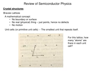
Intrinsic Semiconductors • Q: Why can thermal generation not be used to affect meaningful current conduction? • A: Silicon crystal structure described previously is not sufficiently conductive at room temperature. • Additionally, a dependence on temperature is not desirable. • Q: How can this “problem” be fixed? • A:doping doping – is the intentional introduction of impurities into an extremely pure (intrinsic) semiconductor for the purpose changing carrier concentrations. Lecture 03
Doped Semiconductors A semiconductor material that has been subjected to the doping process is called an extrinsic material. p-type semiconductor • Silicon is doped with element having a valence of 3. • To increase the concentration of holes (p). • One example is boron, which is an acceptor. • n-type semiconductor • Silicon is doped with element having a valence of 5. • To increase the concentration of free electrons (n). • One example is phosophorus, which is a donor. Lecture 03
Doped Semiconductors • p-type semiconductor • n-type semiconductor Lecture 03
N-type p-type Lecture 03
Doped Semiconductors p-type doped semiconductor • If NA is much greater than ni… • concentration of acceptor atoms is NA • Then the concentration of holes in the p-type is defined as below. Lecture 03
Doped Semiconductors n-type doped semiconductor • If ND is much greater than ni… • concentration of donor atoms is ND • Then the concentration of electrons in the n-type is defined as below. The key here is that number of free electrons (conductivity) is dependent on doping concentration, not temperature… Lecture 03
Doped Semiconductors p-type semiconductor • Q:How can one find the concentration? • A:Use the formula to right, adapted for the p-type semiconductor. Lecture 03
Doped Semiconductors n-type semiconductor • Q:How can one find the concentration? • A:Use the formula to right, adapted for the n-type semiconductor. Lecture 03
Doped Semiconductors • p-type semiconductor • np will have the same dependence on temperature as ni2 • the concentration of holes (pn) will be much larger than free electrons • holes are the majority charge carriers • free electrons are the minority charge carrier • n-type semiconductor • pn will have the same dependence on temperature as ni2 • the concentration of free electrons (nn) will be much larger than holes • electrons are the majority charge carriers • holes are the minority charge carrier Lecture 03
Doped Semiconductors It should be emphasized that a piece of n-type or p-type silicon is electrically neutral; the charge of the majority free carriers (electrons in the n-type and holes in the p-type silicon) are neutralizedby the bound charges associated with the impurity atoms. Let no: thermal-equilibrium concentration of electrons po: thermal-equilibrium concentration of holes Nd: concentration of donor atoms Na: concentration of acceptor atoms Nd+ : concentration of positively charged donors (ionized donors) Na- : concentration of negatively charged acceptors (ionized acceptors) Lecture 03
Doped Semiconductors At equilibrium, the product of the majority and minority carrier concentration is a constant, and this is mathematically expressed by the Law of Mass Action. by the charge neutrality condition, n0+ Na- = p0 + Nd+ Lecture 03
Example 2: Doped Semiconductor • Consider an n-type silicon for which the dopant concentration is ND= 1017/cm3. Find the electron and hole concentrations at T = 300K. • Solution The concentration of the majority electrons is The concentration of the minority holes is In Example 1, we found that at T = 300 K, . Thus, Observe that and that is vastly higher than . Lecture 03
Example 3 : Doped Semiconductor For a silicon crystal doped with boron, what must NA be if at T = 300 K the electron concentration drops below the intrinsic level by a factor of 106? Lecture 03
Current Flow in Semiconductors Lecture 03
1. Drift Current There are two distinctly different mechanisms for the movement of charge carriers and hence for current flow in semiconductors: drift and diffusion. • Q:What happens when an electrical field (E) is applied to a semiconductor crystal? • A:Holes are accelerated in the direction of E, free electrons are attracted. • Q:How is the velocity of these carriers defined? Lecture 03
1. Drift Current note that electrons move with velocity 2.5 times higher than holes .E(volts / cm) .mp(cm2/Vs) = 480 for silicon .mn(cm2/Vs) = 1350 for silicon Lecture 03
3.3.1. Drift Current An electric field E established in a bar of silicon causes the holes to drift in the direction of E and the free electrons to drift in the opposite direction. Both the hole and electron drift currents are in the direction of E. • Q:What happens when an electrical field (E) is applied to a semiconductor crystal? • A:Holes are accelerated in the direction of E, free electrons are repelled. • Q:How is the velocity of these holes defined? HOLES ELECTRONS Lecture 03
Current and Current Density Current density may be related to the velocity of volume charge density at a point. Consider the element of charge , as shown in Figure (a). Lecture 03
Current and Current Density • To simplify the explanation, assume that the charge element is oriented to the x-axis and has only an x component of velocity . • If the charge element moved a distance in the time interval , as indicated in Figure (b), the resulting current will be Where represents the x component of the velocity v. In terms of current density, we find and in general Lecture 03
1. Drift Current • Assume that, for the single-crystal silicon bar on previous slide, the concentration of holes is defined as pand electrons as n. • Q: What is the current component attributed to the flow of holes (not electrons)? Lecture 03
1. Drift Current • step #1: Consider a plane perpendicular to the x direction. • step #2: Define the hole charge that crosses this plane. Lecture 03
PART A: What is the current component attributed to the flow of holes (not electrons)? 1. Drift Current • step #3: Substitute inmpE. • step #4: Define current density as Jp = Ip / A. Lecture 03
1. Drift Current • Q: What is the current component attributed to the flow of electrons (not holes)? • A:to the right… • Q: How is total drift current defined? • A:to the right… Lecture 03
1. Drift Current Lecture 03
1. Drift Current • conductivity(s.)– relates current density (J) and electrical field (E) • resistivity(r.)– relates current density (J) and electrical field (E) Lecture 03
Example 4: Drift current • Q(a): Find the resistivity of intrinsic silicon using following values – mn = 1350cm2/Vs,mp= 480cm2/Vs,ni = 1.5x10¹⁰/cm3. • Q(b): Find the resistivity of p-type silicon with NA = 1016/cm2 and using the following values – mn = 1110cm2/Vs,mp= 400cm2/Vs, ni = 1.5x10¹⁰/cm3 note that doping reduces carrier mobility Lecture 03
Example 5: Drift current p = n = ni= 1.5 × 10¹⁰ ⁄ cm3 (a) For intrinsic silicon, (b) For the p-type silicon Lecture 03
Note… • for intrinsic semiconductor– number of free electrons is ni and number of holes is pi • for p-type doped semiconductor– number of free electrons is np and number of holes is pp • for n-type doped semiconductor–number of free electrons is nn and number of holes is pn majority charge carriers minority charge carriers Lecture 03
Example 6: Drift current A uniform bar of n-type silicon of 2 μm length has a voltage of 1 V applied across it. If and .s, find (a) the electron drift velocity, (b) the time it takes an electron to cross the 2-μm length, (c) the drift-current density, and (d) the drift current in the case the silicon bar has a cross sectional area of . Lecture 03
Example 6: Drift current, contd. length c. The current density is given by A Lecture 03
2. Diffusion Current • carrier diffusion– isthe flow of charge carriers from area of high concentration to low concentration. • It requires non-uniform distribution of carriers. • diffusion current– is the current flow that results from diffusion. Lecture 03
2. Diffusion Current • Take the following example… • inject holes– By some unspecified process, one injects holes in to the left side of a silicon bar. • concentration profile arises – Because of this continuous hole inject, a concentration profile arises. • diffusion occurs–Because of this concentration gradient, holes will flow from left to right. diffusion occurs inject holes concentration profile arises Lecture 03
2. Diffusion Current • Q: How is diffusion current defined? Unit: A/cm2 Lecture 03
2. Diffusion Current Observe that a negative (dn/dx) gives rise to a negative current, a result of the convention that the positive direction of current is taken to be that of the flow of positive charge (and opposite to that of the flow of negative charge). Lecture 03
Example 7: Diffusion current • Consider a bar of silicon in which a hole concentration p(x) described below is established. • Q(a):Find the hole-current density Jp at x = 0. • Q(b):Find current Ip. • Note the following parameters: p0 = 1016/cm3, Lp = 1mm, A = 100mm2 Lecture 03
Example 7: Diffusion current, contd. Lecture 03
3. Relationship Between D and m.? • Q:What is the relationship between diffusion constant (D) and mobility (m)? • A:thermal voltage (VT) • Q: What is this value? • A:at T = 300K, VT = 25.9mV known as Einstein Relationship Lecture 03
Summary of Semiconductor currents • drift current density (Jdrift) • affected by – an electric field (E). • diffusion current density (Jdiff) • affected by – concentration gradient in free electrons and holes. Lecture 03
4. The pn Junction with Open-Circuit Terminals4.1. Physical Structure pn junction structure • p-type semiconductor • n-type semiconductor • metal contact for connection Simplified physical structure of the pn junction. As the pn junction implements the junction diode, its terminals are labeled anode and cathode. Lecture 03
4.2. Operation withOpen-Circuit Terminals • Q:What is state of pnjunction with open-circuit terminals? • A: Read the below… • p-type material contains majority of holes • these holes are neutralized by equal amount of bound negative charge • n-type material contains majority of free electrons • these electrons are neutralized by equal amount of bound positive charge Lecture 03
4.2. Operation with Open-Circuit Terminals bound charge • charge of opposite polarity to free electrons / holes of a given material • neutralizes the electrical charge of these majority carriers • does not affect concentration gradients free electrons free holes positive bound charges negative bound charges p-type n-type Lecture 03 Figure: The pn junction with no applied voltage (open-circuited terminals).
4.2. Operation with Open-Circuit Terminals • Q: What happens when a pn-junction is newly formed – aka. when the p-type and n-type semiconductors first touch one another? • A: See following slides… Lecture 03
Step #1: The p-type and n-type semiconductors are joined at the junction. p-type semiconductor filled with holes n-type semiconductor filled with free electrons junction Figure: The pn junction with no applied voltage (open-circuited terminals). Lecture 03
Step #2: Diffusion begins. Those free electrons and holes which are closest to the junction will recombine and, essentially, eliminate one another. p-type n-type Figure: The pn junction with no applied voltage (open-circuited terminals). Lecture 03
Step #3: The depletion region begins to form – as diffusion occurs and free electrons recombine with holes. The depletion region is filled with “uncovered” bound charges – who have lost the majority carriers to which they were linked. p-type n-type Figure: The pn junction with no applied voltage (open-circuited terminals). Lecture 03
Step #4: The “uncovered” bound charges affect a voltage differential across the depletion region. The magnitude of this barrier voltage (V0) differential grows, as diffusion continues. No voltage differential exists across regions of the pn-junction outside of the depletion region because of the neutralizing effect of positive and negative bound charges. voltage potential barrier voltage (Vo) p-type n-type location (x) Lecture 03
Step #5: The barrier voltage (V0) is an electric field whose polarity opposes the direction of diffusion current (ID). As the magnitude of V0 increases, the magnitude of ID decreases. diffusion current (ID) drift current (IS) p-type n-type Figure: The pn junction with no applied voltage (open-circuited terminals). Lecture 03