Download
1 / 10
100 likes | 207 Views
Disk testing - status. Disk Test Setup. we use similar setup as the one used for sector tests, only simplified (no C6F14 cooling system, no source test, no thermo cycling) it is based on TPLL, TPCC, SURF board, ISEG HV (8 channels) running TurboDAQ & Ambush

E N D
Disk Test Setup • we use similar setup as the one used for sector tests, only simplified (no C6F14 cooling system, no source test, no thermo cycling) • it is based on TPLL, TPCC, SURF board, ISEG HV (8 channels) running TurboDAQ & Ambush • Power supplies are not GPIB controlled • cable length of ~20ft (6m) does not cause any problem so far… • (TPCC-SURF board, LV, HV, USB) • at this moment we test only 1 module on the sector but it could be • extended if more sophisticated cooling ensured (air flow fan-out)
Testing – reduced set of sector tests • Following tests have been used (so far): • SRAM digital scan • DFIFO digital scan • Column pair digital scan • Threshold scan (HV=150V) • Threshold scan (antikill mode) • Crosstalk scan • We skipped HV I-V scan, source scan,… • We use module configuration files created at significantly lower temp (~16 degr.C) and our tests are done at temperature ~28 degr.C however doesn’t seem to be a problem
IR2 IR1
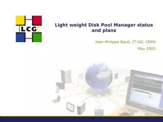
IR1 image – cooling applied (air flow ~50ft3/h) NTC= 29 degr.C
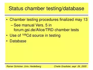
IR2 image – no cooling applied (valve closed) NTC= 35 degr.C
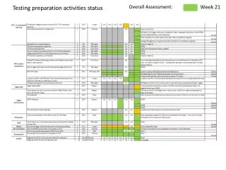
Test results of sector 9017 (top and bottom modules separately)
Next steps • air flow cooling seems to be sufficient way to keep modules at safe • temperature during testing however the cooling setup should be • improve to ensure operation without risk of module damage • ISEG (HV PS) does not seem to be reliable – communication with • PC frequently hanging (fortunately HV stays ON), after restarting of • PC is needed… • we have to check carefully HV current @150V (has not been done • due to ISEG problems) • in principal, we are ready to move the setup to bldg.77 (clean room)