Download
1 / 67
770 likes | 1.12k Views
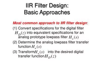
Microwave Filter Design. By Professor Syed Idris Syed Hassan Sch of Elect. & Electron Eng Engineering Campus USM Nibong Tebal 14300 SPS Penang. Contents. Composite filter LC ladder filter Microwave filter. 2. Composite filter.

E N D
Microwave Filter Design By Professor Syed Idris Syed Hassan Sch of Elect. & Electron Eng Engineering Campus USM Nibong Tebal 14300 SPS Penang
Contents • Composite filter • LC ladder filter • Microwave filter 2
Composite filter m<0.6 for m-derived section is to place the pole near the cutoff frequency(wc) For 1/2 p matching network , we choose the Z’1 and Z’2 of the circuit so that 3
Image method Let’s say we have image impedance for the network Zi1 and Zi2 Where Zi1= input impedance at port 1 when port 2 is terminated with Zi2 Zi2= input impedance at port 2 when port 1 is terminated with Zi1 Where Zi2= V2 / I2 Then @ and V1 = -Zi1 I1 4
Image impedance in T and p network Substitute ABCD in terms of Z1 and Z2 Substitute ABCD in terms of Z1 and Z2 Image impedance Image impedance Propagation constant Propagation constant 6
Constant-k section for Low-pass filter using T-network If we define a cutoff frequency And nominal characteristic impedance Zi T= Zo when w=0 Then 8
continue Propagation constant (from page 11), we have • Two regions can be considered • w<wc : passband of filter --> Zit become real and g is imaginary (g= jb ) • since w2/wc2-1<1 • w>wc : stopband of filter_--> Zit become imaginary and g is real (g= a ) • since w2/wc2-1<1 wc a,b stopband passband a wc p Mag b w 9 w
Constant-k section for Low-pass filter using p-network Zi p= Zo when w=0 Propagation constant is the same as T-network 10
Constant-k section for high-pass filter using T-network If we define a cutoff frequency And nominal characteristic impedance Zi T= Zo when w = Then 11
Constant-k section for high-pass filter using p-network Zi p= Zo when w= Propagation constant is the same for both T and p-network 12
m-derived filter T-section Constant-k section suffers from very slow attenuation rate and non-constant image impedance . Thus we replace Z1 and Z2 to Z’1 and Z’2 respectively. Let’s Z’1 = m Z1 and Z’2 to obtain the same ZiT as in constant-k section. Solving for Z’2, we have 14
Low -pass m-derived T-section For constant-k section and Propagation constant where 15
continue If we restrict 0 < m < 1 and Thus, both equation reduces to Then When w < wc, eg is imaginary. Then the wave is propagated in the network. When wc<w <wop, eg is positive and the wave will be attenuated. When w = wop, eg becomes infinity which implies infinity attenuation. When w>wop, then eg become positif but decreasing.,which meant decreasing in attenuation. 16
Comparison between m-derived section and constant-k section M-derived section attenuates rapidly but after w>wop , the attenuation reduces back . By combining the m-derived section and the constant-k will form so called composite filter.This is because the image impedances are nonconstant. 17
High -pass m-derived T-section and Propagation constant where 18
continue Thus wop< wc If we restrict 0 < m < 1 and Thus, both equation reduces to Then When w < wop , eg is positive. Then the wave is gradually attenuated in the networ as function of frequency. When w = wop, eg becomes infinity which implies infinity attenuation. When wc>w >wop, eg is becoming negative and the wave will be propagted. 19
continue a w wop wc M-derived section seem to be resonated at w=wop due to serial LC circuit. By combining the m-derived section and the constant-k will form composite filter which will act as proper highpass filter. 20
m-derived filter p-section Note that The image impedance is 21
Low -pass m-derived p-section For constant-k section Then and Therefore, the image impedance reduces to The best result for m is 0.6which give a good constant Zip . This type of m-derived section can be used at input and output of the filter to provide constant impedance matching to or from Zo . 22
Matching between constant-k and m-derived The image impedance ZiT does not match Zip, I.e The matching can be done by using half- p section as shown below and the image impedance should be Zi1= ZiT and Zi2=Zip It can be shown that Note that 24
Example #1 Design a low-pass composite filter with cutoff frequency of 2GHz and impedance of 75W . Place the infinite attenuation pole at 2.05GHz, and plot the frequency response from 0 to 4GHz. Solution For high f- cutoff constant -k T - section or Rearrange for wc and substituting, we have 25
continue For m-derived T section sharp cutoff 26
continue For matching section m=0.6 27
continue A full circuit of the filter 28
continue Pole due to m=0.2195 section Pole due to m=0.6 section 30
N-section LC ladder circuit(low-pass filter prototypes) Prototype beginning with serial element Prototype beginning with shunt element 31
Type of responses for n-section prototype filter • Maximally flat or Butterworth • Equal ripple or Chebyshev • Elliptic function • Linear phase Equal ripple Elliptic Linear phase Maximally flat 32
Maximally flat or Butterworth filter For low -pass power ratio response Prototype elements Series R=Zo g0 = gn+1 = 1 Shunt G=1/Zo where C=1 for -3dB cutoff point n= order of filter wc= cutoff frequency Series element No of order (or no of elements) Shunt element k= 1,2,3…….n 33 Where A is the attenuation at w1 point and w1>wc
Example #2 Calculate the inductance and capacitance values for a maximally-flat low-pass filter that has a 3dB bandwidth of 400MHz. The filter is to be connected to 50 ohm source and load impedance.The filter must has a high attenuation of 20 dB at 1 GHz. Solution Prototype values g0 = g 3+1 = 1 First , determine the number of elements 34 Thus choose an integer value , I.e n=3
continue 35
or 36
Equi-ripple filter For low -pass power ratio response Chebyshev polinomial where Cn(x)=Chebyshev polinomial for n order and argument of x n= order of filter wc= cutoff frequency Fo=constant related to passband ripple 37 Where Lr is the ripple attenuation in pass-band
Continue Prototype elements where Series element Shunt element 38
Example #3 Design a 3 section Chebyshev low-pass filter that has a ripple of 0.05dB and cutoff frequency of 1 GHz. From the formula given we have F1=1.4626 F2= 1.1371 a1=1.0 a2=2.0 b1=2.043 g1 = g3 = 0.8794 g2= 1.1132 39
Transformation from low-pass to high-pass • Series inductor Lk must be replaced by capacitor C’k • Shunts capacitor Ck must be replaced by inductor L’k 40
Transformation from low-pass to band-pass and where • Now we consider the series inductor normalized • Thus , series inductor Lk must be replaced by serial Lsk and Csk Impedance= series 41
continue Now we consider the shunt capacitor • Shunts capacitor Ck must be replaced by parallel Lpk and Cpk Admittance= parallel 42
Transformation from low-pass to band-stop and where • Now we consider the series inductor --convert to admittance • Thus , series inductor Lk must be replaced by parallel Lpk and Cskp • admittance = parallel 43
Continue Now we consider the shunt capacitor --> convert to impedance • Shunts capacitor Ck must be replaced by parallel Lpk and Cpk 44
Example #4 Design a band-pass filter having a 0.5 dB ripple response, with N=3. The center frequency is 1GHz, the bandwidth is 10%, and the impedance is 50W. Solution From table 8.4 Pozar pg 452. go=1 , g1=1.5963, g2=1.0967, g3= 1.5963, g4= 1.000 Let’s first and third elements are equivalent to series inductance and g1=g3, thus 45
continue Second element is equivalent to parallel capacitance, thus 46
Implementation in microstripline Equivalent circuit A short transmission line can be equated to T and p circuit of lumped circuit. Thus from ABCD parameter( refer to Fooks and Zakareviius ‘Microwave Engineering using microstrip circuits” pg 31-34), we have Model for series inductor with fringing capacitors Model for shunt capacitor with fringing inductors 47
p-model with C as fringing capacitance T-model with L as fringing inductance ZoC should be low impedance ZoL should be high impedance 48
Example #5 From example #3, we have the solution for low-pass Chebyshev of ripple 0.5dB at 1GHz, Design a filter using in microstrip on FR4 (er=4.5 h=1.5mm) Let’s choose ZoL=100W and ZoC =20 W. Note: For more accurate calculate for difference Zo 49
continue The new values for L1=L3= 7nH-0.75nH= 6.25nH and C2=3.543pF-0.369pF=3.174pF Thus the corrected value for d1,d2 and d3 are More may be needed to obtain sufficiently stable solutions 50