Download
1 / 35
350 likes | 415 Views
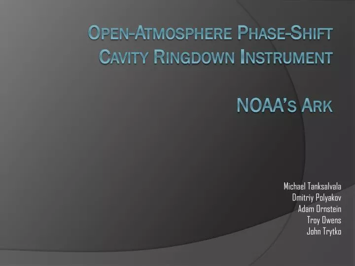
Michael Tanksalvala Dmitriy Polyakov Adam Ornstein Troy Owens John Trytko. Open-Atmosphere Phase-Shift Cavity Ringdown Instrument NOAA’s Ark. Overview.

E N D
Michael Tanksalvala Dmitriy Polyakov Adam Ornstein Troy Owens John Trytko Open-Atmosphere Phase-Shift Cavity Ringdown InstrumentNOAA’s Ark
Overview • The system measures the phase shift of light to determine the concentration of particles in the air (higher concentration yields greater phase shift). • This is used in conjunction with other instruments to compute specific concentrations of various aerosols. • The project is being developed in cooperation with the National Oceanic and Atmospheric Administration (NOAA). Dmitriy John Michael Adam Troy
Objectives • Low Level • Detect optical ringdown on breadboard • Automatic cavity length adjustment • Save data to memory • Mid-Level • Detect optical phase shift • Automatic cavity alignment • Time stamped data saved to SD card • High Level • Build self-contained unit • Recreate faster-than-light neutrinos • Automatic beam profile correction Dmitriy John Michael Adam Troy
Milestones • Milestone 1 • Show ringdown signal on oscilloscope • Demonstrate microcontroller-based beam-steering and cavity length adjustment • Save sample string to SD card • Milestone 2 • Demonstrate phase shift detector • Automated photo-diode signal maximization • Collect and save formatted data to SD card Dmitriy John Michael Adam Troy
Capstone Exposition • Demonstration 1 • Show output of phase shift detector on oscilloscope • Place dry ice near cavity and show phase shift (voltage) increase • Remove SD card and plot contained data in MATLAB • Demonstration 2 • Connect camera to monitor and photodiode to oscilloscope • Manually misalign mirrors and watch automatic readjustment • Demonstration 3 (if possible) • Insert SD card, turn on system, initiate data acquisition • Place self-contained unit near dry ice • Turn off system, take out SD card, plot data in MATLAB Dmitriy John Michael Adam Troy
Laser Safety • Class 3b (continuous wave, 50 mW) • Visible wavelengths (633 or 680 nm) • High power/area (~200 mW/cm2) • Precautions • Never look into laser • Do not open testing area designated by curtain • Laser safety signs will be posted Dmitriy John Michael Adam Troy
Level 1 Design Optical Generation and Signal Detection Atmosphere • Measure and record phase shift over several hours. • Send the photodiode output to the phase shift detector unit. • Output the camera data to alignment system. • Output phase shift data to the data storage system. • Alignment system directly controls mirrors. Data Storage And User I/O Automatic Alignment User Input SD Card SD Card (Data) Clock Display Dmitriy John Michael Adam Troy
Level 2 Design OS R G B ALGN Dmitriy John Michael Adam Troy SD
Level 2 Design (Optics) Dmitriy John Michael Adam Troy
Optical System • Objective: Determine the concentration of aerosol particles within the cavity. • Optical system uses amplitude-modulated laser signal within a cavity to determine the phase shift the cavity introduces. • Ringdown cavity simulates effective length of several kilometers through the use of highly reflective mirrors. John Dmitriy Michael Adam Troy
Optical Modules • Laser Controller • Input: On if instrument is on. • Output: Intensity modulated sine wave (~50 kHz) via laser to cavity and initial phase shift signal to phase shift detector. • Testing: Modulating the laser at a low frequency (~1 Hz) will be visible on a matte surface. Higher frequencies can be verified with a photodiode and an oscilloscope. • Laser Cavity • Resonates laser with two concave mirrors. • Outputs ringdown signal to photodiode. • Testing: Shine output into photodiode. Connect photodiode to oscilloscope. Measure photodiode output on scope, and look for a quick rise followed by an exponential decay. Dmitriy John Michael Adam Troy
Optical Modules • Photodiode • Input: Laser beam from ringdown cavity, 12 volt bias voltage. • Sensitive to both wavelengths we are considering (633, 680 nm) • Output: current passed to phase shift detector. • Mirror mounts • Front: 99.97% reflection, 0.01% transmission. Rear: .2% T • Concave mirrors, 1 m focal length, 6.35 mm thick. • Input: One 0-30 V signal per quadrant. To turn mirror to the left, apply a positive voltage to the right two quadrants. • Testing: Aim laser at mirror mount, with the reflection hitting a far wall. Apply 0 V across one side of the piezo and 30 V across the other. Watch for beam movement. Dmitriy John Michael Adam Troy
Optical Modules (cont) • Phase shift detector • Integrates initial phase shift and final phase shift. • Input: Photodiode voltage, initial signal from laser controller. • Output: Voltage (representing phase shift) to microcontroller. Dmitriy John Michael Adam Troy
Level 2 Design (Alignment) R G B ALGN Dmitriy JohnMichael Adam Troy
Active Feedback/Alignment • Objective: Maintain maximum signal power • Keeps beam pointed at photodiode • If signal is lost, methodically scans over area to try to find it • Concave mirrors provide small amount of passive beam alignment • Uses PID Controller to maintain beam location John Dmitriy Michael Adam Troy
Alignment Modules • CMOS Camera • Outputs NTSC Signal on single signal line • Output must be separated into red, green, and blue components • Signal Extractor • Converts single-channel NTSC to three signals with which the microcontroller and monitor can interface • Implementation: a quadrature detector • Mirror Mount Voltage Amplifiers • Input: Microcontroller voltage (0-5 V) • Output: Mirror Mount voltage (0-30 V) R G B John Dmitriy Michael Adam Troy
Alignment Modules (cont) • Microcontroller • 28 x Piccolo C2000 • 40-80 MHz • Reads pixel values from signal extractor • Thresholded average pinpoints beam location • PID Controller aims beam at desired location • Simpler algorithms maximize signal strength by optimizing desired beam location. • Manual interface to alter desired position and call basic functions ALGN John Dmitriy Michael Adam Troy
Alignment Software Initialization Photodiode (PD) Voltage > (prev_volts * .9)? No Yes Correct Beam Mode Optimize Beam Position Yes Beam Missing PD? Beam Sweep No Optimize Cavity Length Optimize Beam Position prev_volts = PD Voltage John Dmitriy MichaelAdam Troy
Alignment Software Modules • Correct Beam Mode • Detect the positions of the most intense locations on the beam profile • Use lookup table to correlate this to beam mode type and find solution • Testing: Connect the camera output to a monitor. Manually induce different beam modes by altering cavity length and alignment, run function, and watch for the beam profile to turn Gaussian. • Optimize Beam Position • Loop: Bump mirror 1 in last successful direction (end on failed_dir==4) • If photodiode voltage decreases, reverse the movement and increment last successful direction and failed_dir. else, failed_dir = 0; • Testing: Connect photodiode to multimeter. Point beam at photodiode and run program. Watch for photodiode output increase. • Beam Sweep • Move mirror 2 (coarse mirror) in grid pattern, searching for a photodiode signal. • Stop when signal is found. • Testing: Connect photodiode output to multimeter. Turn beam away from photodiode, run the function, and watch for the photodiode output to increase. John Dmitriy Michael Adam Troy
Alignment Software Modules • Optimize Cavity Length • Increase voltage across all quadrants uniformly, searching for a power maximum. If the function finds no oscillatory behavior, the laser is misaligned. Call Beam Sweep. • Testing: Manually adjust cavity alignment and length to get good signal. Mess up alignment. Call function and watch photodiode output increase. • Beam Missing PD? • Goal: see if beam is pointed at photodiode. • Essentially the same as Optimize Cavity Length, but alters the cavity length minimally, to test for voltage fluctuations. • If the voltage decreases in at least one direction, output false. John Dmitriy Michael Adam Troy
Level 2 Design (OS) OS ALGN Dmitriy JohnMichael Adam Troy SD
Operating System • Objective: Store data to file in SD Card • Reads Timestamp from atomic clock chip • Measures phase shift as analog voltage • Measures valid bit as analog voltage • Stores these to comma-delimited text file • <timestamp>,<phase>,<valid> Dmitriy JohnMichael Adam Troy
Data Flow START /STOP ADC Alignment External Clock collectData =START =!STOP Phase Valid Time File Formatted SD Card Buffer SD Card LCD Dmitriy JohnMichael Adam Troy
Operating System Initialization Scheduler No Close File If Open collectData == START ? Yes SD Buffer Empty? SD Buffer Full? Push Time to LCD Yes No No Yes New Data? Write to SD Card No Yes Write to SD Buffer John Dmitriy Michael Adam Troy
SD Card • Contains files with gathered data • Standardized portable memory • FAT32 file system Image obtained from: http://alumni.cs.ucr.edu/~amitra/sdcard/Additional/sdcard_appnote_foust.pdf/ John Dmitriy MichaelAdam Troy
External Clock • Antenna • Receives Atomic Clock Signal • Receiver • Decodes Antenna Signal • Microcontroller Decoder • Outputs time in RS232 Image obtained from: http://alumni.cs.ucr.edu/~amitra/sdcard/Additional/sdcard_appnote_foust.pdf/ John Dmitriy MichaelAdam Troy
User I/O • Inputs • Power Switch • Start / Stop Button • Outputs • LCD display– Time • Blinking – Not collecting data • Green LED – Working • Red LED – Error John Dmitriy MichaelAdam Troy
Power System • Laser Controller – 3 V, 50 mA • Camera - DC 12 V, 50 mA • Photodiode - 12 V, 50 mA • Phase Shift Detector - 12 V, 50 mA • Microcontroller (2x) - Core Supply: 3.3 Volts, I/O Supply: 1.8 Volts • Mirror Mount Voltage Amplifier – 30 V John Dmitriy Michael Adam Troy
Potential Issues / Contingency Plans • Phase shift detector doesn’t work • Plan: Software alternative • Not able to integrate OS with optics • Plan: demonstrate the systems separately at Expo • Beam size too large for camera to measure position • Plan: Use quadrant detector • Beam power too low • For photodiode: Right Bumper to pick up Spartan Laser • For camera: Use quadrant detector • Complicated OS doesn’t work • Plan: Use previously-developed simple OS • SD card Interface does not work • Plan: save to onboard flash memory John Dmitriy Michael Adam Troy
DivisionofLabor John Dmitriy Michael Adam Troy
Schedule John Dmitriy Michael Adam Troy
Parts List John Dmitriy Michael Adam Troy
FundingandGrants • NOAA • Providing optical parts (mirrors, mounts, laser controller, optical breadboard, laser) • Will keep the prototype upon completion • Additional Funding • Received $1,000 from UROP • Any necessary additional money will be gathered from generous donations from team members. John Dmitriy Michael Adam Troy
Questions? John Dmitriy Michael Adam Troy