Download
1 / 18
190 likes | 386 Views
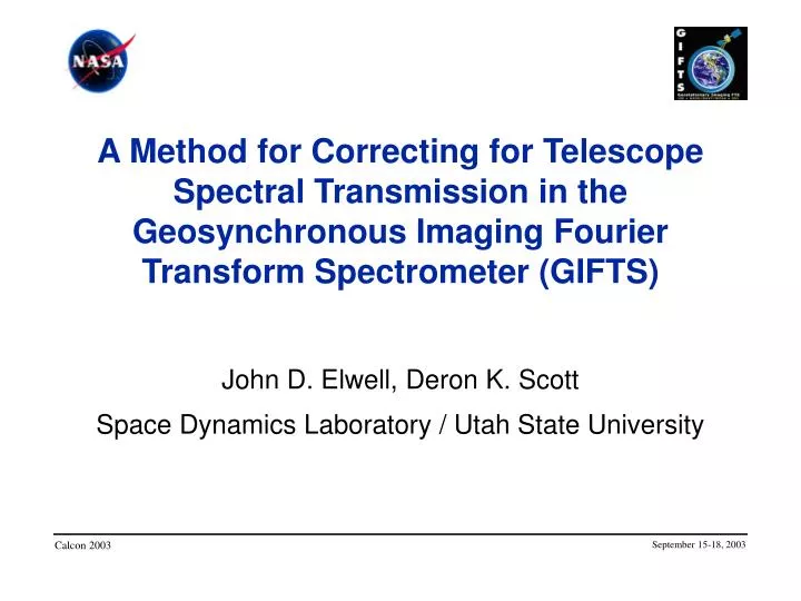
A Method for Correcting for Telescope Spectral Transmission in the Geosynchronous Imaging Fourier Transform Spectrometer (GIFTS). John D. Elwell, Deron K. Scott Space Dynamics Laboratory / Utah State University. Calcon 2003. September 15-18, 2003. GIFTS.

E N D
A Method for Correcting for Telescope Spectral Transmission in the Geosynchronous Imaging Fourier Transform Spectrometer (GIFTS) John D. Elwell, Deron K. Scott Space Dynamics Laboratory / Utah State University Calcon 2003 September 15-18, 2003
GIFTS • GIFTS mission is to provide water vapor, wind, temperature, and trace gas profiles from geosynchronous orbit • Requires highly accurate radiometric and spectral calibration • Radiometric calibration will be performed during ground calibration and updated in-flight using two on-board cavity blackbody in-flight calibrators (IFCs) and cold space • Presentation describes how we will correct for two terms in the responsivity calibration September 15-18, 2003
GIFTS Imaging Interferometer Specifications • Two IR focal planes • Short/midwave • 4.4 to 6.1 mm • 1 K absolute accuracy for scenes >240 K • Longwave • 8.8 to 14.6 mm • 1 K absolute accuracy for scenes >190 K • 128 x 128 pixels, 110 mm pitch, 4-km pixel footprints at nadir • 7 spectral resolutions from 0.6 cm-1 to 38 cm-1 • 0.2 K reproducibility September 15-18, 2003
GIFTS Optical Schematic Pointing Mirror Rear Optics IFC Fold Mirror M1 M2 Det Bpm Bpm Bpm Cf Bm tm tpm tm1 tm2 Bstr tt Bh, eh Bc, ec Hot & Cold In-flight calibrators Structure around IFCs Rf Definitions of terms t?Transmissions (reflectances) of elements e?Emissivities of elements B? Planck radiances at element temperatures Cf Complex response to emissions of the rear optics Rf System responsivity September 15-18, 2003
Pointing Mirror Rear Optics IFC Fold Mirror M1 M2 Det Bpm Bpm Bpm Cf Bm tm tpm tm1 tm2 Bstr tt Bh, eh Bc, ec Hot & Cold In-flight calibrators Structure around IFCs Rf GIFTS Optical Schematic • Need to correct for: • t – signal transmission of the telescope mirrors • m – transmission of the blackbody pick-off mirror September 15-18, 2003
Radiometric Calibration Scene radiance using inflight calibrators1: where: N Computed scene radiance Bh, Bc Planck radiances of hot and cold references eh, ec Emissivities of hot and cold references (assumed equal) Bs Planck function of cold space (effectively 0 for GIFTS) Ch, Cc, Ce, Cs, Cf Measured responses to hot and cold reference, scene, space, and structure (Back end temperatures assumed constant between IFC views) tmBlackbody viewing mirror transmission (assumed constant temp) ttTelescope transmission (reflectivity) 1 Revercomb, et al., “On Orbit Calibration of the Geostationary Imaging Fourier Transform Spectrometer (GIFTS)”, Calcon 200 September 15-18, 2003
tm and tt Measurement • Fold mirror tm and telescope tt will change during flight, and such changes must be periodically measured • The experiments for deriving tt and tm will be performed quarterly September 15-18, 2003
Assumptions Made in Measuring tm and tt • Absorption of gold-coated aluminum telescope mirrors is negligible • Mirror reflectivities (transmissions) can be computed if mirror emissivitiesare known • Mirror emissivities can be estimated by measuring mirror emissions and the mirror temperatures • tmcan be determined in-flight by viewing either IFC at two different fold mirror temperatures September 15-18, 2003
Measuring tm Experimentally • Collect data viewing an in-flight calibrator at two different flip-in mirror temperatures • By taking the difference of measured emissions at two different fold mirror temperatures, tm can be computed as: • Bm1, Bm2, Cm1, Cm2 are the Planck radiances and the measured responses to the cold blackbody with the fold mirror at two different temperatures September 15-18, 2003
tm Uncertainties • Principle uncertainties in measuring tm September 15-18, 2003
Measuring tt Experimentally • Collect a minimum of three measurements with each optical element at different temperatures • The following steps will be performed to collect data • Turn off telescope cooling loop and collect data for 24 hours • Collect emission data by viewing cold space • After each emissions data collection, close the fold mirror and collect tail-end optics emissions data by looking at the cold blackbody September 15-18, 2003
Deriving tt • Cold space response: Bs Planck radiance of space (4 K), assumed to be 0 tt Telescope transmission Lt Total emission from telescope Rf System responsivity Cf Complex emission from optics behind the telescope With Bs=0, the unknowns are the telescope emission, Lt, and the complex emissions from the rear optics, Cf September 15-18, 2003
Deriving tt • Cf can be measured for each telescope emission measurement by looking at the cold IFC • Lt, total telescope emission, is the sum: • This can be linearized with the substitutions: September 15-18, 2003
Deriving tt A set of simultaneous linear equations can be set up to solve for Lt • The values on the left side are known • The B values are computed from element temperatures • With more than three samples, these equations are then solved using a least-squared error approach for a1, a2, and a3 • The resulting mirror emissivities can be computed as: September 15-18, 2003
tt Uncertainties • Principle uncertainties in measuring tt September 15-18, 2003
Overall Radiance Calibration • The combined uncertainty of the radiance calibration and derivation of tt and tm has been modeled September 15-18, 2003
Responsivity must be computed seperately for each pixel, therefore multiple scans must be collected to do any averaging • tm and tt are applicable to all pixels • A single scan of interferometer data will provide about 16000 samples over which tm and tt can be averaged • Still to be addressed • Residual nonlinearity • Changes in responsivity over 24-hour telescope thermal cycle September 15-18, 2003