1 / 42

Instrumentation Amplifier Noise Analysis

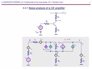
Instrumentation Amplifier Noise Analysis. Short Review of 3 Amp INA. Three Stage IA. Real World Input to Mathematical Model. Analyze the Input and Output Separately. Split Input Stage in Half. Use Superposition on Output Amp. Gain For Three Amp IA. Noise Model of 3 Amp INA.

eamon
Download Presentation

Instrumentation Amplifier Noise Analysis

An Image/Link below is provided (as is) to download presentation Download Policy: Content on the Website is provided to you AS IS for your information and personal use and may not be sold / licensed / shared on other websites without getting consent from its author. Content is provided to you AS IS for your information and personal use only. Download presentation by click this link. While downloading, if for some reason you are not able to download a presentation, the publisher may have deleted the file from their server. During download, if you can't get a presentation, the file might be deleted by the publisher.

E N D

Presentation Transcript


  1. Instrumentation Amplifier Noise Analysis

  2. Short Review of 3 Amp INA

  3. Three Stage IA

  4. Real World Input to Mathematical Model

  5. Analyze the Input and Output Separately

  6. Split Input Stage in Half

  7. Use Superposition on Output Amp

  8. Gain For Three Amp IA

  9. Noise Model of 3 Amp INA

  10. Complex Noise Model

  11. The Complex Model is Simplified

  12. The Input amplifier dominates at High Gain

  13. Two Ways to represent INA Spectral Density Calculated using graphs and formula Taken directly from the graph

  14. Hand Analysis of 3 Amp INA

  15. Find the total RMS Noise Voltage at the Output

  16. Look at Noise Sources: Bridge, INA333, Reference Buffer

  17. Noise Equivalent Model for Reference Pin Buffer

  18. Reference buffer

  19. The reference voltage directly adds to the output noise

  20. The bridge generates: thermal noise, in x R_bridge

  21. Noise From Bridge / Current Sources

  22. Combine all the noise sources

  23. Rule of 3x

  24. Bandwidth from Data Sheet For G = 100 20dB/decade 1st order Kn = 1.57

  25. Calculate RMS Output Noise for INA333 From Voltage Noise

  26. Simulation of 3 Amp INA

  27. Simulate the Circuit

  28. Using Tina Spice

  29. Noise Spectral Density at the Output

  30. Total RMS Noise at the Output

  31. Why doesn’t calculation match simulation exactly? Bandwidth from Data Sheet and simulated bandwidth is different. The roll-off was approximated as first order in the calculations. Simulation shows that it is not first order.

  32. Reduce Noise Using Averaging Circuit

  33. Averaging Circuit

  34. Noise in Averaging Circuit

  35. Averaging Circuit with INA333

  36. Experiment with 20 Parallel INA333 20 INA333 amps in parallel (jumper selectable) Socketed Gain Set Resistors OPA333 Averaging Circuit

  37. Standard Noise Measurement Precautions Linear Power Source Steel Paint Can for Shielding

  38. Total Output Noise vs Number of Amplifiers Being Averaged

  39. Measured vs simulated spectral density

  40. References • [1] Hann, Gina. "Selecting the right op amp - Electronic Products." Electronic Products Magazine – Component and Technology News. 21 Nov. 2008. Web. 09 Dec. 2009. <http://www2.electronicproducts.com/Selecting_the_right_op_amp-article-facntexas_nov2008-html.aspx>. • Henry W. Ott, Noise Reduction Techniques in Electronics Systems, John Wiley and Sons Acknowledgments: • R. Burt, Technique for Computing Noise based on Data Sheet Curves, General Noise Information • T. Green, General Information • B. Trump, General Information • Matt Hann, General INA information and review Noise Article Series (www.en-genius.net) http://www.en-genius.net/site/zones/audiovideoZONE/technical_notes/avt_022508

  41. Thank You for Your Interest in INA Noise – Calculation and Measurement

More Related