Download
1 / 69
700 likes | 862 Views
Chapter 4 Components and Circuits. Electrical Review Current is the flow of electrons and is measured in amperes or amps (A) with an ammeter. Voltage is the potential that moves electrons and is measured in volts (V) with a voltmeter.

E N D
Chapter 4Components and Circuits Electrical Review • Current is the flow of electrons and is measured in amperes or amps (A) with an ammeter. • Voltage is the potential that moves electrons and is measured in volts (V) with a voltmeter. • Resistance is the opposition to current flow and is measured in ohms (Ω) with a ohmmeter. • Power is the energy use (or generation) per unit time and is measured in watts (W).
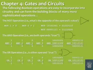
Ohm’s Law (E = voltage, I = current, R = resistance) • Power (P = power)
Metric Prefixes • milli (m) = 1/1,000 = 10-3 • kilo (k) = 1,000 = 103 • mega (M) = 1,000,000 = 106 • Micro (μ) = 1/1,000,000 = 10-6 • nano (n) = 1/1,000,000,000 = 10-9 • pico (p) = 1/1,000,000,000,000 = 10-12 • Examples: • Calculate the resistance that would draw 10 mA with an applied voltage of 15 V. • Calculate the power dissipated by a 200 Ω resistor with a current of 1.5 A flowing through it. • Calculate the voltage drop across the above resistor.
AC and DC Waveforms • Direct current (DC) flows in one direction. The voltage maintains the same polarity. • Alternating current (AC) reverses direction. The voltage polarity changes regularly. • AC is represented by a sine wave (1 cycle or wavelength is shown)
, where λis the wavelength (meters, m), f is the frequency (Hertz, Hz), and c is the speed of light (3×10⁸m/sec) • Examples • Calculate the wavelength of 29.6 MHz signal. • Calculate the frequency of a 75 meter signal.
Decibels • A bel is logarithmic unit expression the ratio of a quantity such as power or sound intensity. A bel is a large unit so the decibel (dB) is used. Deci is the metric prefix for 1/10, so a decibel is one tenth of a bel.
Examples • Calculate the gain in dB of an amplifier that amplifies a 1 W signal to a 20 W signal. • Calculate the power in dBm of a 10 W signal. • Calculate the dB ratio that represents a doubling of the power. • Calculate the fraction of the original transmitter power that gets to an antenna with 2 dB of loss in the coax running to the antenna.
AC Power • An AC signal varies over the course of a cycle from zero to a positive peak, back to zero, then a negative peak and back to zero again.
For a given DC voltage in a circuit that is dissipating a given power, the equivalent AC voltage with same power dissipation is called the RMS (root mean square) voltage.
Examples • Calculate the RMS voltage for VPeak = 120 V • Calculate the VPeak-Peak when VRMS = 12 V. • Peak Envelope Power (PEP) is the average power over over one RF cycle at the peak of the signal’s (audio) envelope.
Peak Envelope Voltage (PEV) is one half the peak to peak voltage. • For an AC signal, power, voltage, and current are related by the same equations as DC, but using PEP power, VRMS and IRMS. • The average power in an umodulated AM signal is the PEP power. Key down average power in CW is also PEP power. • Examples • If an oscilloscope measures a 150 VP-P voltage across a 50 Ω load, calculate the PEP power. • What is the RMS voltage across a 50 Ω load dissipating 100 W PEP?
Basic Components • Electrical components are described by the following; • Nominal value (for example 75 Ω resistor) • Tolerance describes a range over which the manufacturer specifies the component value (for example +/-5%). • Temperature coefficient is the gives the components variation with temperature. • Power/voltage/current rating is a maximum rating that the component can handle without overheating or shorting out.
Resistors • Thermistors are resistors with a calibrated change in resistance with temperature and can be used a temperature sensor.
Inductors store energy in a magnetic field created when a current flows through them. • Inductors resist a change in current flow and therefore will act like a low pass filter.
Inductors have inductance. The unit of inductance is the Henry (H). • Inductors can filter high frequencies out of a power supply’s output. They are called filter chokes. • Wirewound resistors have a parasitic inductance which limits their use at radio frequencies. Use carbon, or metal oxide resistors at radio frequencies. • An iron core in an inductor increases the inductance over an equivalent air wound inductor. • The core material in an inductor can saturate at high frequencies. The core material has an optimized frequency range.
Mutual inductance is the transfer of magnetic energy between two inductors. It is used to advantage in transformers. In radio circuits, mutual inductance is not desirable and can be avoided by placing inductors are right angles to each other or using toroidal cores.
Capacitors are constructed from two parallel metal plates and store energy in the electric field between the plates. An applied voltage establishes the electric field. • Capacitors are defined by their capacitance, which is measured in Farads (F). • The metal plates of a capacitor have a dielectric insulating material between them. The dielectric can be air, mylar, or other insulating materials.
Inductors, which have parallel windings can have a parasitic capacitance. • Capacitors can have parasitic inductance. The leads can have parasitic inductance also. • Ceramic capacitors are low cost and usable through VHF and UHF (with some parasitic lead inductance). • Electrolytic capacitors are used in power supplies for filtering.
Series and Parallel Circuits • Kirchoff’s Voltage Law (KVL) – The voltages around a circuit must add up to the applied voltage. • Kirchoff’s Current Law (KCL) – The total current entering a junction must equal the sum of the currents leaving the junction.
For two resistors in parallel, you can use the simpler formula; • The same formula will work for capacitors in series and inductors in parallel. • Examples • Calculate the equivalent resistance of three 150 Ω resistors in parallel.
Examples (continued) • Calculate the equivalent inductance of a 30 mH and 25 mH inductor in series. • Calculate the equivalent capacitance of a 20 μF, 50 μF, and a 35 μF capacitor in series • Calculate the equivalent resistance of a 500 pF and 1000 pF capacitor in parallel.
Transformers use mutual inductance between two inductors to transform AC voltages. Power is applied to the primary winding and extracted from the secondary winding. • Voltage transformation depends on the number of windings of the primary and secondary.
Example • Calculate the secondary voltage if the applied voltage is 120 V ac, the primary has 500 turns, and the secondary has 2000 turns. • What turns ratio would be required to transform 120 V ac to 1000 V ac?
Reactance and Impedance • Resistors resist the flow of AC current the same for all frequencies. • Inductors and capacitors resist the flow of AC current in a frequency dependent way. • Reactance is the measure of the resistance to AC by inductors and capacitors. Reactance is measured in ohms and uses the symbol X. Reactance is caused by the property of inductors and capacitors to store energy.
Examples • Calculate the capacitive reactance of a 2nF capacitor at 3 MHz. • Calculate the inductive reactance of a 10 mH inductor at 1 MHz. • Impedance, Z, is the combined effect of resistance and reactances in a circuit. Impedance is also measured in ohms.
Resonance occurs when a circuit (or antenna) is purely resistive with no reactance. This occurs when capacitive reactance equals inductive reactance. • The figure below shows a series resonant circuit.
Maximum power transfer occurs when the impedance of the source equals the impedance of the load. An impedance matching LC circuit can be used between a transmitter and an antenna to improve the power transfer.
Impedances can be matched using a transformer. • Example • What turns ratio is required to transform a 200 Ω impedance to a 40 Ω impedance? • Impedances can be matched using special lengths of transmission lines.
Semiconductor Components • Semiconductors are made from Silicon (Si) or Germanium (Ge) with added elements, such as Indium (In) or Phosphorus (P), called dopants. These dopants create either an N-type semiconductor, or P-type semiconductor. • N-type semiconductors conduct electricity with electrons • P-type semiconductors conduct electricity with “holes”, which are positive charges caused by a missing electron bond.
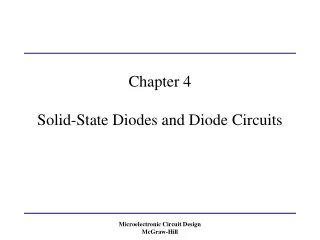
Diodes • A diode is the simplest semiconductor device and is formed from a PN junction. • The junction threshold voltage, VF, is typically 0.3 V for germanium and 0.7 V for silicon.
Forward bias is when the positive voltage is applied to the P-type material (anode) and the negative voltage is applied to the N-type material (cathode). A large current can flow in forward bias. • Reverse bias is the opposite polarity from forward bias and no current flows. • The ratings for a semiconductor diode are; • Peak Inverse Voltage (PIV) is the largest reverse voltage a diode can withstand before reverse breakdown occurs.
Average Forward Current is the limiting current before a diode will overheat. The dissipated power is IF×VF. • The junction of a diode also has some capacitance. A varactor diode is a special diode designed to act a voltage variable capacitor. • Schottky diodes use a metal for the N-material and are useful at very high frequencies (1012 Hz). • Zener diodes are used as voltage regulators due to their precise reverse breakdown voltage. • PIN diodes have a VF and are used for switching.
Bipolar and Field Effect Transistors • Bipolar Junction Transistors (BJT) are formed with three layers, PNP or NPN.
The three electrodes of a BJT transistor are the collector (C), base (B), and emitter (E). • The base current controls the collector-emitter current flow. • Field Effect Transistors (FET) also have three terminals, drain (D), source (S), and gate (G). The gate voltage controls the drain-source current.
A junction FET (JFET) has the junction in contact with the channel.
Metal-Oxide-Semiconductor FET (MOSFET) and Insulated-Gate FET (IGFET) have an insulating layer between the gate and channel. • The high gain of transistors (FET’s and BJT’s) make them excellent as switches in digital circuits. • High power transistors have metal cases to improve heat dissipation. Be careful when installing such transistors to avoid short circuits.
Vacuum Tubes • Vacuum tubes were used before transistors were available.
The filament or heater heats the cathode so that it emits electrons. • The cathode emits electrons. • The control grid controls the flow of electrons from the cathode to the plate. • The screen grid reduces the grid-plate capacitance which diminishes high frequency performance. • The suppressor grid prevents electrons from traveling from the plate to the other grids. • The plate collects the electrons from the cathode. This is called the plate current. • FET’s are analogous in operation to a vacuum tube.
Analog and Digital Integrated Circuits • An integrated circuit (IC) or “chip” is a collection of transistors, diodes, resistors, capacitors, and inductors on a single wafer of silicon. • Analog IC’s operate over a continuous range of voltages or currents. • Operational Amplifiers (Op Amps) are inexpensive amplifiers for DC and audio circuits. • Linear Voltage Regulators are used in power supplies to provide a regulated voltage.
Digital IC’s operate at two discrete values of voltage representing on or off (the binary values of 1 or 0). • Logic families • Resistor Transistor Logic (RTL) is no longer used. • Transistor Transistor Logic (TTL) is still in use but not for low power circuits. • Complementary Metal Oxide Semiconductor (CMOS) Logic is very high speed with low power consumption.
Digital circuits are combinations of gates. • Flip-flops can be connected together to create shift registers and counters. • A shift register can store binary data. • A counter can count up to 2N where N is the number of shift registers. A 4 bit (N = 4) counter can count to 24 = 2 × 2 × 2 × 2 = 16. • Microprocessors contain thousands of gates on a single chip. • Microcontrollers have interfaces for external signal and control circuits.
Digital Interfaces • Serial interfaces process data one bit (1 or 0) at a time. • RS232 (COM port) • USB (Universal Serial Bus) has replaced the RS232 port • Network (WiFi, Ethernet, Bluetooth) • Parallel Interfaces process several bits at a time. • Parallel port (LPT or line printer port).
Visual Interfaces • Cathode Ray Tube (CRT) • Liquid Crystal Display (LCD) are very low power but have no light. LCD displays require an external light source. • Light Emitting Diode (LED) is a PN junction diode which emits light when forward biased. • RF Integrated Circuits • Monolithic Microwave Integrated Circuit (MMIC) are used in cell phones and GPS receivers.