Download
1 / 65
950 likes | 1.59k Views
EEE 531: Semiconductor Device Theory I Instructor: Dragica Vasileska Department of Electrical Engineering Arizona State University. Topics covered: Energy bands Effective masses. Energy bands. Basic convention:. Kinetic energy: Potential Energy:. +E. K.E. E C. P.E. E v. E ref. +V.

E N D
EEE 531: Semiconductor Device Theory I Instructor: Dragica Vasileska Department of Electrical Engineering Arizona State University • Topics covered: • Energy bands • Effective masses
Energy bands Basic convention: Kinetic energy: Potential Energy: +E K.E. EC P.E. Ev Eref +V Electric field:
Energy-wavevector relation for free electrons: Definition: de Broglie hypothesis: Energy-wavevector relation for electrons in a crystal: The dispersion relation in a crystal (E-k relation) is obtained by solving the Schrödinger wave equation:
Bloch Theorem: If the potential energy V(r) is periodic, then the solutions of the SWE are of the form: where un(k,r) is periodic in r with the periodicity of the direct lattice and n is the band index. Methods used to calculate the energy band structure: • Tight-binding method • Orthogonal plane-wave method • Pseudopotential method • k•p method • Density functional technique (DFT)
Periodic potential Bloch function Cell periodic Part Plane wave component
Reciprocal Space: A 1D periodic function: can be expanded in a Fourier series: The Fourier components are defined on a discrete set of periodically arranged points (analogy: frequencies) in a reciprocal space to coordinate space. 3D Generalization: Where hkl are integers. G=Reciprocal lattice vector
First Brillouin Zone (in reciprocal space): • The periodic set of allowed points corresponding to the Fourier (reciprocal) space associated with the real (space) lattice form a periodic lattice • The Wigner-Seitz unit cell corresponding to the reciprocal lattice is the First Brillouin Zone • is zone center, L is on zone face in (111) direction, X is on face in (100) direction First Brillouin Zone for Zinc- Blende and Diamond real space FCC lattices
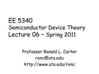
Examples of energy band structures: GaAs Si Based on the energy band structure, semiconductors can be classified into: Indirect band-gap semiconductors (Si, Ge) Direct band gap semiconductors (GaAs)
Model Energy Bands in III-V and IV Semiconductors: • Conduction Band - 3 Valley Model (, L, X minima). Lowest minima: X (Si), L (Ge), (GaAs, most III-Vs) • Valence Band - Light hole, heavy hole, spin-split off band
Si Ge GaAs Eg (eV) 1.12 0.66 1.42 • The energy band-gaps decrease with increasing temperature. The variation of the energy band-gaps with temperature can be expressed with a universal function:
Effective Masses Curvature of the band determines the effective mass of the carriers in a crystal, which is different from the free electron mass. Smaller curvature heavier mass Larger curvature lighter mass • For parabolic bands, the components of the effective mass tensor are calculated according to: Si
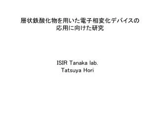
From the knowledge of the energy band structure, one can construct the plot for the allowed k-values associated with a given energy => constant energy surfaces Ge Si Note:The electron effective mass in GaAs is isotropic, which leads to spherically symmetric constant energy surfaces.
Due to the p-like symmetry and mixing of the V.B. states, the constant energy surfaces are warped spheres: The hh-band is most warped The lh- and so-band are more spherical Constant energy surfaces Valence bands
EEE 531: Semiconductor Device Theory I Instructor: Dragica Vasileska Department of Electrical Engineering Arizona State University • Topics covered: • Counting states • Density of states function • Density of states effective mass • Conductivity effective mass
Introductory comments -Counting states: • Let us consider a one-dimensional chain of atoms: • According to Bloch theorem, the solutions of the 1D SWE for periodic potential are of the form: • The application of periodic boundary conditions, leads to: • the allowed k-values are: a a a L =Na length of the chain
Note on the boundary conditions: • If one employs vanishing boundary conditions, it would give as solutions standing waves (sinx or cosx functions), which do not describecurrent carrying states. • Periodic boundary conditions lead to traveling-wave (eikx) solutions, which represent current carrying states. • Counting of the states: • Each atom in the 1D chain contributes one state (two if we account for the spin: spin-up and spin-down states). • The difference between two adjacent allowed k values is: Length in the reciprocal space associated with one state (2 if we account for the spin)
In 3D, the unit volume in the reciprocal space associated with one state is (not accounting for spin). • Calculation of the DOS function: • Consider a sphere in k-space with volume: • The total number of states we can accommodate in this volume is: • The # of states in a shell of radius k and thickness dk is, by similar arguments, equal to:
# of states per unit length dk • Use the fact that the number of states is conserved, i.e. • where • For parabolic energy bands, for which E=2k2/2m* Spin degeneracy # of states per unit volume per unit energy interval dE around E
E gC(E) EC EV gV(E) • DOS effective masses: • For single valley and parabolic bands, the DOS function in 3D equals to: for electrons in the conduction band for holes in the valence band
For many-valley semiconductors with anisotropic effective mass, using Herring-Vogt transformation: • the expression for the density of states function reduces to the one for the single valley case, except for the fact that one has to use the density of states effective mass: • Si (electrons): • Z(# of equivalent valleys)=6, ml=0.98m0, mt=0.19m0 • GaAs (electrons): <= isotropic mass density of states effective mass
For holes, which occupy the light-hole (lh) and heavy-hole (hh) bands, the effective DOS mass equals to: • Si (holes): • GaAs (holes): • Side note: • For two-dimensional (2D) and one-dimensional (1D) systems, one has:
Conductivity effective mass: • Consider a many-valley semiconductor, such as Si: • Under the assumption that the • valleys are equally populated, • the electron density in each • valley equals n/6. • The total current density equals the sum of the contributi-ons from each valley separately, i.e. 3 1 2 2 1 3
The contribution from an individual valley is given by: • Thus, the total current density equals to: Conductivity tensor Effective mass tensor The conductivity effective mass is used for mobility calculations!
EEE 531: Semiconductor Device Theory I Instructor: Dragica Vasileska Department of Electrical Engineering Arizona State University • Topics covered: • Drift (mobility, drift velocity, Hall effect) • Diffusion • Generation-recombination mechanisms
Drift process: • Under low-field conditions, the carrier drift velocity is proportional to the electric field: • vdn=-mnF (for electrons) and vdp=mpF (for holes) • These expressions can be obtained from the second law of motion. For example, for an electron moving in an electric field, one has: • Low frequency limit:
t=0 t= tm (tm=10-14-10-12 s) t= tE (tE=10-13-10-11 s) • The linear dependence of v on F does not hold at high fields when electrons gain considerable energy from the electric field, in which case one has: • Description of the momentum relaxation timetmand energy relaxation timetE:
Drift velocity for GaAs and Si: Intervalley transfer GaAs Silicon Slope dvd/dF=m
Small devices => non-stationary transport • velocity overshoot=> faster devices (smaller transit time) Velocity overshoot effect Silicon
Carrier Mobility: Ionized impurities Si, GaAs Acoustic phonons Si, GaAs polar optical phonons GaAs neutral impurities (low T) Si, GaAs Piezoelectric (low-T) GaAs Non-polar optical phonons Si Mathiessen’s rule:
Carrier Mobility (Cont’d): Electron mobility
Drift velocity in Si: (A) Electrons: Saturation velocity:
Hall measurements: • Resistivity measurements • carrier concentration characterization • low-field mobility (Hall mobility)
The second law of motion for an electron moving in a electric and magnetic field, at low frequencies is of the form: • One also has: • Hall coefficient: • where rn is the Hall scattering factor: • Determine n • Sign=>carrier type
The effective carrier mobility is obtained in the following manner: • 1. Calculate the conductivity of the sample: • 2. Evaluate the Hall mobility: • 3. Based on the knowledge of the Hall scattering factor, • determine the effective mobility using:
p(x) + Diffusion process: n(x) - • Dn, DpDiffusion constants for electrons and holes • Totalcurrent equals the sum of the drift and diffusion components:
Einstein relations (derivation): • Assumptions: • equilibrium conditions • non-degenerate semiconductor
Generation-Recombination Mechanisms: • Photons and phonons (review): • Photonsquantum of energy in an electromagnetic wave • Phononsquantum of energy in an elastic wave
Generation-Recombination mechanisms: Notation: g generation rate rrecombination rate R=r-g net recombination rate Importance: BJTs R plays a crucial role in the operation of the device Unipolar devices (MOSFET’s, MESFETs, Schottky diodes No influence except when investigating high-field and breakdown phenomena
Photogeneration • Radiative recombination • Direct thermal generation • Direct thermal recombination One step (Direct) Two-step (indirect) Energy-level consideration Two particle • Shockley-Read-Hall (SRH) generation-recombination • Surface generation-recombination Impact ionization Auger Pure generation process Three particle • Electron emission • Hole emission • Electron capture • Hole capture Classification:
(1) Direct processes Diagramatic description: Ec Ec Ec Ec Light E=hf heat heat Light Ev Ev Ev Ev x Photo- generation Radiative recombination Direct thermal generation Direct thermal recombination Not the usual means by which the carriers are generated or recombine • Important for: • narrow-gap semiconductors • direct band-gap SCs used for fabricating LEDs for optical communications
E E Virtual states Phonon emission Ec Phonon absorption Eg Eg EV k k Direct band-gap SCs Indirect band-gap SCs • Photogeneration band-diagramatic description: • Momentum and energy conservation: photon phonon final initial final initial photon
Light intensity Distance 1/a light-penetration depth Near the absorption edge, the absorption coefficient can be expressed as: hf= photon energy Eg = bandgap g = constant g=1/2 and 1/3 for allowed direct transitions and forbidden direct transitions g=2 for indirect transitions where phonons are involved
Photogeneration-radiative recombination mathematical description • - Both types of carriers are involved in the process • - Limiting cases: • (a) Low-level injection: • (b) High-level injection:
(2) Auger processes: Diagramatic description: Ec Ec Ec Ec Ev Ev Ev Ev Electron capture Hole capture Electron emission Hole emission Generation process (energetic carriers involved) Recombination process (carriers near the band edges involved) • Auger generation takes place in regions with high concent-ration of mobile carriers with negligible current flow • Impact ionization requires non-negligible current flow
Auger process mathematical description • - Three carriers are involved in the process • - Limiting cases (p-type sample): • (a) Low-level injection: • (b) High-level injection:
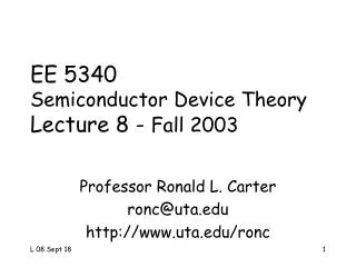
- Auger Coefficients: (Silvaco) (3) Impact ionization: Diagramatic description identical to Auger generation Ionization rates => generated electron hole- pairs per unit length of travel per carrier
1 0.35 (b) 0.25 0.8 0.18 0.6 Average energy [eV] 0.15 0.4 0.2 0 0.3 0.4 0.5 0.6 0.7 m Distance along the channel [ m] - Ionization rates dependence upon the electric field component parallel to the current flow: Impact ionization VG=3.3 V, VD =3.3, 2.5, 1.8 and 1.5 V
Ec ET Electron capture Hole capture Ev (4) Shockley-Read-Hall Mechanism: Diagramatic description: Mathematical model: Ec Ec nT cn en Electron emission pT ET ET nT Hole emission cp ep pT Ev Ev Generation Recombination Two types of carriers involved in the process
- Thermal equilibrium conditions: - Steady-state conditions: n1 and p1 are the electron and hole densities when EF=ET