Download
1 / 53
570 likes | 636 Views
ECEN 667 Power System Stability. Lecture 17: Transient Stability Solutions, Load Models. Prof. Tom Overbye Dept. of Electrical and Computer Engineering Texas A&M University, overbye@tamu.edu. Announcements. Read Chapter 7 Homework 5 is due today

E N D
ECEN 667 Power System Stability Lecture 17: Transient Stability Solutions,Load Models Prof. Tom Overbye Dept. of Electrical and Computer Engineering Texas A&M University, overbye@tamu.edu
Announcements • Read Chapter 7 • Homework 5 is due today • Homework 6 is assigned today, due on Nov 9 • Final is as per TAMU schedule. That is, Friday Dec 8 from 3 to 5pm
Nonlinear Network Equations • With constant impedance loads the network equations can usually be written with I independent of V, then they can be solved directly (as we've been doing) • In general this is not the case, with constant power loads one common example • Hence a nonlinear solution with Newton's method is used • We'll generalize the dependence on the algebraic variables, replacing V by y since they may include other values beyond just the bus voltages
Nonlinear Network Equations • Just like in the power flow, the complex equations are rewritten, here as a real current and a reactive currentYV – I(x,y) = 0 • The values for bus i are • For each bus we add two new variables and two new equations • If an infinite bus is modeled then its variables and equations are omitted since its voltage is fixed This is a rectangularformulation; we alsocould have writtenthe equations inpolar form
Nonlinear Network Equations • The network variables and equations are then In general thereare no slack buses
Network Equation JacobianMatrix • The most computationally intensive part of the algorithm is determining and factoring the Jacobian matrix, J(y)
Network Jacobian Matrix • The Jacobian matrix can be stored and computed using a 2 by 2 block matrix structure • The portion of the 2 by 2 entries just from the Ybus are • The major source of the current vector voltage sensitivity comes from non-constant impedance loads; also dc transmission lines The "hat" wasadded to the g functions to indicate it is justthe portion fromthe Ybus
Example: Constant Current and Constant Power Load • As an example, assume the load at bus k is represented with a ZIP model • The constant impedance portion is embedded in the Ybus • Usually solved in per unit on network MVA base The base loadvalues areset from the power flow
Example: Constant Current and Constant Power Load • The current is then • Multiply the numerator and denominator by VDK+jVQK to write as the real current and the reactive current
Example: Constant Current and Constant Power Load • The Jacobian entries are then found by differentiating with respect to VDK and VQK • Only affect the 2 by 2 block diagonal values • Usually constant current and constant power models are replaced by a constant impedance model if the voltage goes too low, like during a fault
Example: 7.4.ZIP Case • Example 7.4 is modified so the loads are represented by a model with 30% constant power, 30% constant current and 40% constant impedance • In PowerWorld load models can be entered in a number of different ways; a tedious but simple approach is to specify a model for each individual load • Right click on the load symbol to display the Load Options dialog, select Stability, and select WSCC to enter a ZIP model, in which p1&q1 are the normalized about of constant impedance load, p2&q2 the amount of constant current load, and p3&q3 the amount of constant power load Case is Example_7_4_ZIP
Example 7.4.ZIP Bus 8 Load Values • As an example the values for bus 8 are given (per unit, 100 MVA base)
Example: 7.4.ZIP Case • For this case the 2 by 2 block between buses 8 and 7 is • And between 8 and 9 is • The 2 by 2 block for the bus 8 diagonal is These entries areeasily checkedwith the Ybus The check here is left for the student
Additional Comments • When coding Jacobian values, a good way to check that the entries are correct is to make sure that for a small perturbation about the solution the Newton's method has quadratic convergence • When running the simulation the Jacobian is actually seldom rebuilt and refactored • If the Jacobian is not too bad it will still converge • To converge Newton's method needs a good initial guess, which is usually the last time step solution • Convergence can be an issue following large system disturbances, such as a fault
Simultaneous Implicit • The other major solution approach is the simultaneous implicit in which the algebraic and differential equations are solved simultaneously • This method has the advantage of being numerically stable
Simultaneous Implicit • Recalling the second lecture, we covered two common implicit integration approaches for solving • Backward Euler • Trapezoidal • We'll just consider trapezoidal, but for nonlinear cases
Nonlinear Trapezoidal • We can use Newton's method to solve withthe trapezoidal • We are solving for x(t+Dt); x(t) is known • The Jacobian matrix is Right now weare just consideringthe differentialequations; we'll introducethe algebraicequationsshortly The –I comesfrom differentiating -x(t+Dt)
Nonlinear Trapezoidal usingNewton's Method • The full solution would be at each time step • Set the initial guess for x(t+Dt) as x(t), and initialize the iteration counter k = 0 • Determine the mismatch at each iteration k as • Determine the Jacobianmatrix • Solve • Iterate until done
Infinite Bus GENCLS Example • Use the previous two bus system with gen 4 again modeled with a classical model with Xd'=0.3, H=3 and D=0 In this example Xth = (0.22 + 0.3), with the internal voltage giving E'1=1.281 and d1=
Infinite Bus GENCLS Implicit Solution • Assume a solid three phase fault is applied at the bus 1 generator terminal, reducing PE1 to zero during the fault, and then the fault is self-cleared at time Tclear, resulting in the post-fault system being identical to the pre-fault system • During the fault-on time the equations reduce to That is, with a solid fault on the terminal of the generator, duringthe fault PE1 = 0
Infinite Bus GENCLS Implicit Solution • The initial conditions are • Let Dt = 0.02 seconds • During the fault the Jacobian is • Set the initial guess for x(0.02) as x(0), and
Infinite Bus GENCLS Implicit Solution • Then calculate the initial mismatch • With x(0.02)(0) = x(0) this becomes • Then
Infinite Bus GENCLS Implicit Solution • Repeating for the next iteration • Hence we have converged with
Infinite Bus GENCLS Implicit Solution • Iteration continues until t = Tclear, assumed to be 0.1 seconds in this example • At this point, when the fault is self-cleared, the equations change, requiring a re-evaluation of f(x(Tclear))
Infinite Bus GENCLS Implicit Solution • With the change in f(x) the Jacobian also changes • Iteration for x(0.12) is as before, except using the new function and the new Jacobian This also converges quickly, with one or two iterations
Computational Considerations • As presented for a large system most of the computation is associated with updating and factoring the Jacobian. But the Jacobian actually changes little and hence seldom needs to be rebuilt/factored • Rather than using x(t) as the initial guess for x(t+Dt), prediction can be used when previous values are available
Two Bus Results • The below graph shows the generator angle for varying values of Dt; recall the implicit method is numerically stable
Adding the Algebraic Constraints • Since the classical model can be formulated with all the values on the network reference frame, initially we just need to add the network equations • We'll again formulate the network equations using the form • As before the complex equations will be expressed using two real equations, with voltages and currents expressed in rectangular coordinates
Adding the Algebraic Constraints • The network equations are as before
Classical Model Coupling of x and y • In the simultaneous implicit method x and y are determined simultaneously; hence in the Jacobian we need to determine the dependence of the network equations on x, and the state equations on y • With the classical model the Norton current depends on x as Recall with the classicalmodel Ei’ is constant
Classical Model Coupling of x and y • In the state equations the coupling with y is recognized by noting
Variables and Mismatch Equations • In solving the Newton algorithm the variables now include x and y (recalling that here y is just the vector of the real and imaginary bus voltages • The mismatch equations now include the state integration equations • And the algebraic equations
Jacobian Matrix • Since the h(x,y) and g(x,y) are coupled, the Jacobian is • With the classical model the coupling is the Norton current at bus i depends on di (i.e., x) and the electrical power (PEi) in the swing equation depends on VDi and VQi (i.e., y)
Jacobian Matrix Entries • The dependence of the Norton current injections on d is • In the Jacobian the sign is flipped because we defined
Jacobian Matrix Entries • The dependence of the swing equation on the generator terminal voltage is
Two Bus, Two Gen GENCLS Example • We'll reconsider the two bus, two generator case from Lecture 16; fault at Bus 1, cleared after 0.06 seconds • Initial conditions and Ybus are as covered in Lecture 16 PowerWorld Case B2_CLS_2Gen
Two Bus, Two Gen GENCLS Example • Initial terminal voltages are
Results Comparison • The below graph compares the angle for the generator at bus 1 using Dt=0.02 between RK2 and the Implicit Trapezoidal; also Implicit with Dt=0.06
Four Bus Comparison Fault at Bus 3 for 0.12 seconds; self-cleared
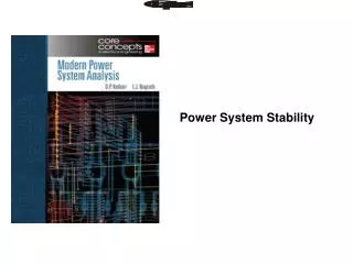
Done with Transient Stability Solutions: On to Load Modeling • Load modeling is certainly challenging! • For large system models an aggregate load can consist of many thousands of individual devices • The load is constantly changing, with key diurnal and temperature variations • For example, a higher percentage of lighting load at night, more air conditioner load on hot days • Load model behavior can be quite complex during the low voltages that may occur in transient stability • Testing aggregate load models for extreme conditions is not feasible – we need to wait for disturbances!
Load Modeling • Traditionally load models have been divided into two groups • Static: load is a algebraic function of bus voltage and sometimes frequency • Dynamic: load is represented with a dynamic model, with induction motor models the most common • The simplest load model is a static constant impedance • Has been widely used • Allowed the Ybus to be reduced, eliminating essentially all non-generator buses • Presents no issues as voltage falls to zero • Is rapidly falling out of favor
Load Modeling References • Many papers and reports are available! • A classic reference on load modeling is by the IEEE Task Force on Load Representation for Dynamic Performance, "Load Representation for Dynamic Performance Analysis," IEEE Trans. on Power Systems, May 1993, pp. 472-482 • A more recent report that provides a good overview is "Final Project Report Loading Modeling Transmission Research" from Lawrence Berkeley National Lab, March 2010
ZIP Load Model • Another common static load model is the ZIP, in which the load is represented as • Some models allow more general voltage dependence The voltage exponent for reactive power is often > 2
ZIP Model Coefficients • An interesting paper on the experimental determination of the ZIP parameters is A. Bokhari, et. al., "Experimental Determination of the ZIP Coefficients for Modern Residential and Commercial Loads, and Industrial Loads," IEEE Trans. Power Delivery, 2014 • Presents test results for loads as voltage is varied; also highlights that load behavior changes with newer technologies • Below figure (part of fig 4 of paper), compares real and reactive behavior of light ballast
ZIP Model Coefficients The Z,I,P coefficientssum to zero;note that forsome modelsthe absolutevalues of theparameters are quite large,indicatinga difficult fit A portion of Table VII from Bokhari 2014 paper
Discharge Lighting Models • Discharge lighting (such as fluorescent lamps) is a major portion of the load (10-15%) • Discharge lighting has been modeled for sufficiently high voltage with a real power as constant current and reactive power with a high voltage dependence • Linear reduction for voltage between 0.65 and 0.75 pu • Extinguished (i.e., no load) for voltages below May need to changewith newer electronicballasts – e.g., reactivepower increasing asthe voltage drops!