Download
1 / 20
210 likes | 458 Views
Design, Fabrication, and Test of a TWT Transportable Dual-polarization X-band Radar. Boon Leng Cheong 1,2 , Robert D. Palmer 1,3 , Y. Zhang 1,2 , M. Yeary 1,2 , and T.-Y. Yu 1,2 1 Atmospheric Radar Research Center (ARRC), University of Oklahoma, USA

E N D
Design, Fabrication, and Test of a TWT Transportable Dual-polarization X-band Radar Boon Leng Cheong1,2, Robert D. Palmer1,3, Y. Zhang1,2, M. Yeary1,2, and T.-Y. Yu1,2 1 Atmospheric Radar Research Center (ARRC), University of Oklahoma, USA 2 School of Electrical and Computer Engineering, University of Oklahoma, USA 3 School of Meteorology, University of Oklahoma, USA International Symposium on Radar and Modeling Studies of the Atmosphere
Special thanks go to the Microwave Remote Sensing Laboratory (MRSL) at the University of Massachusetts-Amherst for their assistance in this project
Motivation and Objective • In-house equipment with complete freedom • Small footprint and light weight for transportability • Software define radio • Autonomous • Walk up to it with a laptop, run it, download the (time series) data and leave • Stable transmit phase so no magnetron transmitter • Possibility for sub-pulse and/or inter-pulse phase coding • Avoid waveguide rotary joint • Compatible with CASA nodes
Targeted Radar Specification • An X-band system @ f = 9550 MHz (λ = π cm, 3.14 cm) • 3.5-kW (peak) Traveling Wave Tube (TWT) transmitter • Transmit duty cycle of up to 2% • 4’-parabolic reflector with 1.8° beam • Mechanical scanning of up to 25°/sec • Software defined radio (radar) • Many mixers, filters, modulation/demodulators are implemented in software rather than hardware
Pertinent Issues • X-band: Attenuation, sensitivity, cost, risk, compatibility • Beamwidth of 1.8° • For long range range collection, r = 10 km 350m beamwidth • Transmitter Limitations • Peak power of 3.5 kW • Up to 15 us (2250 m) and < 2% duty cycle • At X-band, va of ~15 m/s => 2 kHz PRF 10 us maximum PW • Fastest scan rate at 30°/sec • Everything above pedestal • Maximum payload of 260 lbs (~120 kg)
Pulse Compression • Increase average transmit power and enhance range resolution • Transmitting a phase-coded, wideband signal • Compressing the return signal through filter • Require the transmitter to operate in higher duty cycle • 2% maximum duty cycle for our 3.5-kW TWT transmitter • Operational WSR-88D uses ~0.16% duty cycle • Blind range • Signals near the radar are not recoverable • One way around this is to alternatively transmit non-coded pulses for short-range echoes Skolnik, M. I., 1990: Radar Handbook. McGraw Hill, 2nd Edition.
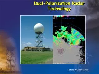
Polarimetric Capabilities • Simultaneously or alternatively transmit and receive two orthogonal linearly polarized EM waves • Real-time moments: • Reflectivity (Z) • Radial Velocity (V) • Spectrum Width (W) • Differential Reflectivity (ZDR) • Differential Phase (PhiDP) • Correlation Coefficient (RhoHV)
Major Components & Vendors • Pedestal AL-4016 from Orbit Communication Systems, Inc. • Reflector C0824-820 from Seavey Engineering Associates, Inc. • TWT amplifier transmitter model 174 from Applied Systems Engineering • Digital transceiver board 7640 from Pentek • Microcontroller MOD5282 from Netburner • A lot of Mini-Circuit components !
Pedestal: Orbit AL-4016 • Azimuth above elevation • Maximum payload: 260 lbs • Motor type: DC brushless • Maximum speed: 30°/sec • Limitation: • Elevation: -5° to 185° • Continuous azimuth • Weight: 300 lbs • Power requirement: 450W • Communication interface: RS422
Antenna: Seavey C0824-820 • Frequency: 9.550 GHz • Diameter: 4 ft (1.2m) • Gain: 38.5 dBi • Beamwidth: 1.8° • Focal length ratio: 18/48 = 0.375 • Cross-pol Isolation: 26 dB • VSWR: 1.25:1, Maximum • Wind load: • 30 mph 48 lbs • 60 mph 194 lbs • 100 mph 538 lbs • We need a radome!
Transmitter: ASE 174X • Traveling Wave Tube • Peak power: 3.5 kW • Frequency: 8.8-10.5 GHz • Pulse width: 15 us, max • PRF: Up to 400 kHz • Duty cycle: 2%, max • Weight: 95 lbs • Control interface: RS232 • Other features: • VSWR protection • Overdrive protection
Orbit AL-4016 with Seavey Antenna • Video of the pedestal
Transceiver: Pentek 7460 • Linux/windows based Software Radio Development • 2 Ch 14-bit A/D, 80-MHz IF sampling (84 dB dynamic range) • 2 Ch 16-bit D/A, 320-MHz digital upconverter
Microcontroller: NetBurner MOD5282 • Generates trigger pulse for the entire system • Behaves as a TCP/IP networked subsystem • 8 low-speed A/D for health monitoring • Voltage monitoring • Temperature sensors • Humidity sensor • GPIO • GPS, digital compass, etc. • Serial ports • Transmitter (via RS232) • Pedestal (via RS422)
Radome: Pacific Radome PR-99 • Loss: <0.3 dB • Bottom opening is sufficiently wide for lifting up • 8-ft wide • Radar on truck is still possible
Software Architecture • Software control for transmit and receive • Scanning patterns, schedules • Transmit waveforms, pulse width, PRT • Receive signal sampling, gate spacing, collection range • Raw I/Q streaming via TCP/IP • Real-time time series signal processor using a computer • All subsystem are networked via TCP/IP connections • Pedestal RS422 microcontroller Ethernet • TWT transmitter RS232 microcontroller Ethernet • Built-in test equipment microcontroller Ethernet • GPS/Digital compass microcontroller