Download
1 / 5
50 likes | 131 Views
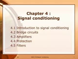
bKLM RPC Signal & Ground Schematic. G erard Visser , Indiana University (for the barrel KLM team) 10th B2GM, 11/2011. Signals are handled — insofar as practical — in a balanced, differential manner. No ground loops. Signal current flow. RPC module aluminum case. plane. 7mm FOAM.

E N D
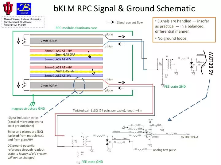
bKLM RPC Signal & Ground Schematic GerardVisser, Indiana University (for the barrel KLM team) 10th B2GM, 11/2011 • Signals are handled — insofar as practical —in a balanced, differential manner. • No ground loops. Signal current flow RPC module aluminum case plane 7mm FOAM strips 3mm GLASS AT +HV 2mm GAS GAP 3mm GLASS AT -HV AS BELOW 3mm GLASS AT +HV 2mm GAS GAP 3mm GLASS AT -HV strips 7mm FOAM FEE crate GND plane magnet structure GND Twisted pair 113Ω (24 pairs per cable), length ≈6m Signal induction strips (parallel microstrip over a solid ground plane) Strips and planes are (DC) isolated from module case and from glass/HV DC ground potential reference through readout crate (a legacy of old system, will not be changed) to TDC FPGA analog test pulse FEE crate GND
bKLM RPC HV schematic 6 more RPC module aluminum case 7mm FOAM HVPS 3mm GLASS AT +HV 2mm GAS GAP 3mm GLASS AT -HV 3mm GLASS AT +HV HVPS 2mm GAS GAP 3mm GLASS AT -HV 7mm FOAM HVPS magnet structure GND HV input cable grounds are NO CONNECT at RPC module electronics hut safety GND • as far as any signals (intentional or EMI) are concerned, HV circuit is all high impedance and no ground loops introduced • positive HV has 8 units fed from one HV channel • negative HV has individual RPC per HV channel • leakage currents drawn from HV (through RPC glass & spacers) is of order 10 μA
bKLM RPC FEE crate/rack locations • No changes from Belle system • 8 readout crates (6U “VME”) on each end of detector, in the indicated racks.
bKLM RPC FEE cable route • Note that although all signals are carried on unshielded twist-n-flat, at least up to exit of magnet everything is obviously very effectively shielded and segregated from other subsystems by the magnet steel. • Reminder the signals are received balanced/differentially, although of course the source impedance is unbalanced. No changes from Belle system
bKLM RPC FEE crate / power • Not (yet) so much to say here on this topic, although it is recognized important. • The goal is to re-use the crates (6U “VME” from ELMA) from Belle system, at most to replace the backplane and/or power supplies. • Backplane is good but 21 slot is more than needed, may limit performance (latency to deliver hit data to trigger system). If so, we’ll replace it, e.g. with a 14-slot backplane. • Supply voltages and currents probably quite different for new design, TBD at present. It may lead to replacing the supplies. • Old system used linear supplies, but if replaced would (likely) use some switching PS. Will evaluate noise carefully, of course... • Conclusions • bKLM RPC should be reasonably immune to EMI from differential signal path design • for the same reason, and due to small (normal) signal size, bKLM RPC should generate no EMI to other subsystems • we are taking this all into account in design and look forward to further discussion and review THANK YOU