Download
1 / 39
410 likes | 1.06k Views
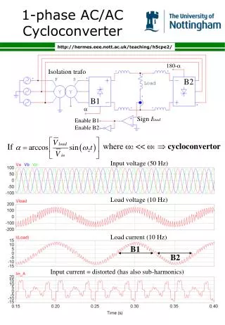
AC Machine Stator. ‘b’ phase axis. 120 0. 120 0. ‘a’ phase axis. 120 0. ‘c’ phase axis. Currents in different phases of AC Machine. t 01. t 12. Amp. t 1. t 2. t 3. t 4. t 0. time. 1 Cycle. MMF Due to ‘a’ phase current . 1. Axis of phase a. 0.8. t 0. 0.6. t 01. 0.4. 0.2.

E N D
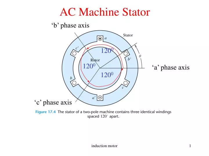
AC Machine Stator ‘b’ phase axis 1200 1200 ‘a’ phase axis 1200 ‘c’ phase axis induction motor
Currents in different phases of AC Machine t01 t12 Amp t1 t2 t3 t4 t0 time 1 Cycle induction motor
MMF Due to ‘a’ phase current 1 Axis of phase a 0.8 t0 0.6 t01 0.4 0.2 Fa a’ a 0 a’ t12 -0.2 -0.4 -0.6 t2 -0.8 -1 -90 -40 10 60 110 160 210 260 Space angle (theta) in degrees induction motor
RMF(Rotating Magnetic Field) a Fc b’ 1.5 c’ Fa F t = t0= t4 F 1 Fa c Fc b 0.5 Fb a’ 0 Fb -0.5 t = t0= t4 -1 -1.5 -93 10 113 216 F Space angle () in degrees Fb Fc a Fb b’ a a c’ b’ b’ c’ c’ Fa c b c c F b b a’ Fc Fc a’ a’ Fb t = t2 t = t3 t = t1 F induction motor
Video of the unfolded rotating magnetic field induction motor
RMF(Rotating Magnetic Field) -Analogy with DC machines The salient field structure in DC machines is mimicked along with speed in an AC machines by a multiphase (2 or more) winding. The number of poles are determined by winding distribution and is independent of the number of phases. The rotational speed is determined by the supply frequency and the number of poles, such that an observer in air-gap counts same number of poles per second, meaning the more the number of poles the slower the machine will run and vice-versa. induction motor
Induction Motor • Most popular motor today in the low and medium horsepower range • Very robust in construction • Speed easily controllable using V/f or Field Oriented Controllers • Have replaced DC Motors in areas where traditional DC Motors • cannot be used such as mining or explosive environments • Of two types depending on motor construction: Squirrel Cage • or Slip Ring • Only Disadvantage: Most of them run with a lagging power factor induction motor
Squirrel Cage Rotor induction motor
Slip Ring Rotor • The rotor contains windings similar to stator. • The connections from rotor are brought out using slip rings that • are rotating with the rotor and carbon brushes that are static. induction motor
Torque Production in an Induction Motor • In a conventional DC machine field is stationary and the current carrying conductors rotate. • We can obtain similar results if we make field structure rotating and current carrying conductor stationary. • In an induction motor the conventional 3-phase winding sets up the rotating magnetic field(RMF) and the rotor carries the current carrying conductors. • An EMF and hence current is induced in the rotor due to the speed difference between the RMF and the rotor, similar to that in a DC motor. • This current produces a torque such that the speed difference between the RMF and rotor is reduced. induction motor
Slip in Induction Motor • However, this speed difference cannot become zero because that would stop generation of the torque producing current itself. • The parameter slip ‘s’ is a measure of this relative speed difference • where ns,s,f1 are the speeds of the RMF in RPM ,rad./sec and supply frequency respectively • n, are the speeds of the motor in RPM and rad./sec respectively • The angular slip frequency and the slip frequency at which voltage is induced in the rotor is given by induction motor
Induction Motor Example A 100 hp, 460V, 8 pole, 60 Hz, star connected 3 phase induction motor runs at 891 rpm under full load. Determine the synchronous speed in rpm, slip, slip frequency (frequency of the rotor circuit),slip rpm at full load. What is the speed of the rotor field relative to (i) rotor structure, (ii) stator structure, (iii) stator rotating field? Voltage induced in rotor under full load? N2/N1=0.5 Solution on Greenboard induction motor
Induction motor Equivalent Circuit induction motor
Internal efficiency = Relation between air-gap, gross mechanical power and rotor copper loss Implies lower the slip higher is the induction motor efficiency induction motor
Example problem related to the formula shown in the previous induction motor
Approximate Equivalent Circuit j • Assumes negligible magnetizing current • Note Rc has been removed. • The sum of core losses and the windage and friction loses are treated • as constant. This is because as speed increases rotor core loss • decreases (lower f2) but windage and frictionloses increase.With • decrease of speed the converse is true. Thus the sum is constant at • any speed and is termed as rotational loss. induction motor
IEEE Equivalent Circuit • Assumes 30-50% magnetizing current and drop across R1+jX1 not • negligible • As before, the sum of core losses and the windage and friction loses are • treated as constant. induction motor
Thevnin’s equivalent of the IEEE Equivalent Circuit • This is done by applying Thevenin’s theorem and treating the rotor • side as load induction motor
j Determining equivalent circuit parameters Uses no-load test and blocked rotor tests to determine them induction motor
Example problem related to no-load and blocked rotor test induction motor
Performance Characteristics(1) induction motor
Performance Characteristics(2) induction motor
Performance Characteristics(3) Case 1: induction motor
Performance Characteristics(4) Case 2: induction motor
Performance Characteristics(5) Combining case 1 and 2 the approximate torque speed characteristics would look approximately like: Tmech Tmax nm ns Speed (n) induction motor
Performance Characteristics(6) How to obtain Tmax? By differentiating the following equation with respect to s and equating it to zero. One can obtain the following: Slip at maximum torque = induction motor
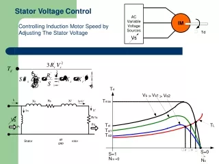
Performance Characteristics(7) (Speed Control) Speed control by varying supply voltage and frequency (Vth/1) (efficient) Speed control by varying rotor resistance (vary Tmax by varying sTmax) (inefficient) induction motor
Performance Characteristics(8) Also using and for small R1 one can write the following: induction motor
Example problem based on the formula on previous to express maximum torque and starting torque in terms of rated torque induction motor
Performance Characteristics(9) induction motor
Example problem related to efficiency calculation of induction motor based on equivalent circuit parameters induction motor
Related to the problem in the previous slide induction motor
Different modes of IM operation induction motor
Different modes of IM operation induction motor
Example problem on variable frequency supply using a slip-ring induction motor induction motor
Speed control of SRIM with ext. resistors induction motor
Applications of SRIM induction motor
Wind Power applications of SRIM induction motor