Download
1 / 53
570 likes | 910 Views
Electrical Machine-II EEN-287 (AC Machine) Engr. Sobuj Kumar Ray Faculty, BSEEE IUBAT. Two Types: Synchronous Machine. Asynchronous Machine. Types of AC Machine. Synchronous Machine : The machine whose speed is alwaysconstant with the increasing load. Ex: Synchronous motor

E N D
Electrical Machine-II EEN-287 (AC Machine) Engr. Sobuj Kumar Ray Faculty, BSEEE IUBAT
Two Types: • Synchronous Machine. • Asynchronous Machine. Types of AC Machine
Synchronous Machine: The machine whose speed is alwaysconstantwith the increasing load. Ex: Synchronous motor (2) Asynchronous Machine: The machine whose speed is not always constant with the increasing load. Ex: Induction motor, Alternator.
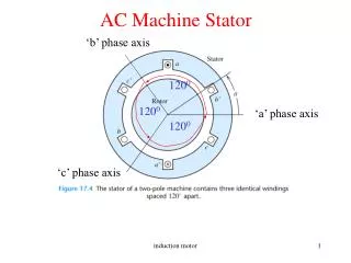
Construction: Induction motor consists essentially of two main parts 1. Stator 2. Rotor Poly-phase ( 3-φ) Induction Motor
Stator: • The stator consists of a cylindrical laminated & slotted core placed in a frame of rolled or cast steel. • It carries a 3-phase winding and is fed from a 3-phase supply. • It is wound for a definite number of poses (determined by the requirement of speed). • Greater the number of poles, lesser the speed and vice versa.
Rotor: The rotor consists of a laminated & slotted core tightly pressed on the shaft. There are two general types of rotors:1. Squirrel-cage rotor2. ‘Phase wound’ or ‘wound’ or ‘slip ring’ rotor. Fig. Rotor for an IM. Fig. Completely wound stator for an IM.
Squirrel-cage Rotor • The rotor consists of a cylindrical laminated core with parallel slots for carrying the rotor conductors which are not wires but consist of heavy bars of copper, aluminium or alloys. • One bar is placed in each slot. • The rotor bars are brazed or electrically welded or bolted to two heavy and stout short-circuited end-rings, thus giving us, what is so picturesquely called, a squirrel-case construction.
Q. Write down the significance of the name ‘squirrel-cage’ in case of squirrel-cage rotor. Phase wound Rotor(‘Phase wound’ or ‘wound’ or ‘slip ring’ rotor): This rotor is provided with 3-φ, double-layer, distributed winding.Q. what is the significance of wound rotor?
Contd. • The rotor is wound for as many poles as the umber of stator poles and is always wound 3-phase even when the stator is wound two-phase. • The three phases are starred internally. The other three winding terminals are brought out and connected to three insulated slip rings mounted on the shaft with brushes resting on them. • 3 brushes are further externally connected to a 3 phase star-connected rheostat.
Production of Rotating Field:( For 2-φ, and 3-φ supply) (For 2- φ) (For 3- φ) B.L. Thereja. Art: 34.6 & 34.7
Why does the Rotor Rotate? • 3-φ stator winding is fed by 3-φ supply • Rotating flux of const. magnitude produced • Flux passes through air-gap & cuts rotor conductor • An emf is induced in rotor conductor • Since rotor bars or conductors from closed circuit, current flows through rotor conductors whose direction, as given by Lenz’s law, is such as to oppose the very cause producing it. • In this case the cause of rotor current is the relative velocity between the rotating stator flux & the stationary rotor conductors. • Hence, to reduce the relative speed, the rotor starts running in the same direction as that of the flux and tries to catch up with the rotating flux. Thus rotor of induction motor rotates
Contd. Fig. Rotation of Rotor of an IM.
Write down the significance of the name “Induction Motor”. • In induction motor, no current is conducted to one of the motor element (field or armature). • The current in one of these elements results from an induced voltage and for that reason it is called Induction motor. • Induction motors are somewhat referred to as asynchronous(meaning not synchronous) machines.
Q. Why induction motor treated as a rotating transformer? • Transformer has two sides: primary & secondary • Transformer transforms energy from primary to secondary by induction • Similarly, Induction motor has primary (stator) & secondary (rotor) • Voltage is induced in secondary by rotating flux of const. magnitude i.e the process of induction Thus induction motor treated as a rotating transformer. Ref: B.L. Thereja. Art: 34.2
Slip The difference between the synchronous speed Ns and the actual rotor speed Nr is known as slip. It is usually expressed as a percentage of the synchronous speed. Sometimes, (Ns - Nr) is called the slip speed. So, the rotor speed Nr = Ns(1-s)
Frequency of Rotor Current • When the rotor is stationary, the frequency of rotor current is the same as the supply frequency. • But when the rotor starts revolving, then the frequency depends upon the relative speed or on slip-speed. • Let at any slip speed, the frequency of the rotor current be f’. Then, Dividing one by the other, we get, So rotor current frequency is f’ =sf
Power Stages in an Induction Motor Mechanical power developed in Rotor, Pm Motor input in stator, P1 Rotor input,P2 Rotor cu & core losses Stator cu & core losses Rotor output, Pout Friction and windage Loss B.L Thereja; Art: 34.34
Problems 1. A 4-pole, 3-phase induction motor operates from a supply whose frequency is 50 Hz. Calculate: • The speed at which the magnetic field of the stator is rotating. • The speed of the rotor when the slip is 0.04. • The frequency of the rotor currents when the slip is 0.03. • The frequency of the rotor currents at standstill. [ Example: 34.3] • 2. An 8-pole alternator runs at 750 r.p.m and supplies power to a 6-pole induction motor which has at full-load a slip of 3%. Find the full-load speed of the induction motor and the frequency of its rotor e.m.f. [ Tutorial: 34.1/3] • In the case of an 8 pole induction motor, the supply frequency was 50 Hz and the shaft speed was 735 rpm. Find out i) synchronous speed, ii) speed of slip • iii) per unit slip iv) percentage sleep. [ Tutorial: 34.1/1] • 4. Example 34.4 (H.W)
Relation between Torque and Rotor Power factor • For dc motor we know that, torque Ta∞ Φ Ia. • Similarly in the case of induction motor, the torque is proportional to the product of flux per stator pole & rotor current. However there is one more factor that has to be taken into account i.e. the power factor of the rotor current. Therefore, T∞Φ I2cos Φ2 => T=kΦ I2cos Φ2 Where, I2= rotor current at standstill Φ2= angle between rotor emf and rotor current. k= constant.
Contd. • Denoting rotor emf at standstill by E2 , we have T∞E2I2cos Φ2 Or, T=k1E2I2cos Φ2 Where, k1 is another constant. And • The effect of rotor power factor is Shown in fig below. We get that if Φ2 increases the torque decreases And vice versa. • Fig. shows the torque assuming resistive rotor.
Starting Torque • Torque developed at the instant of running is called starting torque.
Condition For Maximum Starting Torque • It can be proved that starting torque is maximum when rotor resistance equals rotor reactance.
Starting Torque of Squirrel- Cage Motor • Resistance is fixed & small compared to the reactance • Frequency equals to supply frequency at starting • impedance small, current I2 is large & lags by a very large angle behind E2 • For large power factor angle, the power factor becomes very low. • Hence Starting torque will be small • This motor is not useful where the motor has to start against heavy loads.
Starting Torque of Slip-ring Motor • By improving power factor, starting torque increase • Adding external resistance in rotor circuit from star connected rheostat, impedance increase • impedance Z2 large, current I2 is small • Current I2 lags by small angle behind E2 • For low power factor angle, power factor becomes large. • So, starting torque will be large • This motor is useful where the motor has to start against heavy loads.
Effect of Change in Supply Voltage on Starting Torque • We know that Now Therefore Where k3 is yet another constant. Hence • Clearly, the torque is very sensitive to any changes in the supply voltage. A change of 5% in supply voltage, for example, will produce a change of approximately 10% in the rotor torque.
Rotor EMF and Reactance Under Running Conditions • Let E2= Standstill rotor induced e.m.f./phase X2 = Standstill rotor reactance/phase, f2 = rotor current frequency at standstill • When rotor is stationary then slip s=1 and frequency of rotor e.m.f. is same that of stator supply frequency. • Under running condition, rotor e.m.f. Er = sE2 Frequency of the induced emf fr =sf2 Due to the decrease in frequency of the rotor emf, the rotor reactance Xr=sX2
Contd. C Z2 sX2 Φ2 A B R2
Contd. Slip corresponding to maximum torque is So, maximum torque from equation (1) is
Relation Between Torque and Slip • A family of torque/slip curves is shown in fig.1 below for a range of s=0 to s=1 with R2 as the parameter. We know that • When s=0, T=0, hence the curve starts from point 0. • At normal speeds, close to synchronism, the term (sX2) is small and hence negligible w.r.t. R2.
Contd. • For low value of s, the curve is approx. a straight line. • As s increases (for increasing motor load), the torque increases and becomes maximum at s=R2/X2. This torque is known as “pull-out” or “breakdown” torque or, stalling torque.
Contd. • As the slip is increased further, R2 becomes negligible as compared to (sX2). Thus for large value of slip • Beyond the point of Tmax , any further increase in motor load results in decrease of torque developed. Thus the motor slows down and eventually stops. • The stable operation of the motor lies between the values of s=0 and that corresponding to maximum torque as shown by the orange shaded region.
Effect of Change in Supply Frequency on Speed & Torque • The major effect of change in supply frequency is on motor speed • If frequency drops by 10%, speed also drops 10% • If machine tools & motor-driven equipment for 50 Hz supply connected to 60 Hz supply; • Then; everything runs = 20% faster than the normal. • In such case, we have to use either gears to reduce motor speed or an expensive 50 Hz source
Q. How can a 50 Hz motor operate satisfactory on 60 Hz supply? Ans: • The condition for operating a motor in any supply frequency is should be constant at all times. • When a 50 Hz motor is operated on 60 Hz supply frequency then its terminal voltage is increased to =120% of rated supply
Q. How can a 60 Hz motor operate satisfactory on 50 Hz supply? • The condition for operating a motor in any supply frequency is should be constant at all times. • When a 60 Hz motor is operated on 50 Hz supply frequency then the speed will decrease 16.66 %. • To operate the motor satisfactorily its terminal voltage is reduced to =83.33% of rated supply
Relation Between Full-Load Torque & Maximum Torque • Tf = • Tmax = • If,
Relation Between Starting Torque & Maximum Torque • If, Math: B.L Thereja; Example: 34.15(a), 34.16, 34.24 (V.V.I)
Three regions in torque-speed curve: 1) Plugging (braking) region (1<s<2) Rotor rotates opposite to direction of air gap flux. Can happen, for example, if stator supply phase sequence reversed while rotor is moving. 2) Motoring region (0<s<1) Te=0 at s=0. As s increases (speed decreases),Te increases until max. torque (breakdown) is reached. Beyond this point, Te decreases with increasing s. 3) Regenerating Region (s<0) Here the induction machine acts as a generator. Rotor moves faster than air gap flux resulting in negative slip.
Plugging of an Induction Motor • An induction motor can be quickly stopped by simply interchanging any of its two stator leads. • It reverses the direction of the revolving flux which produces a torque in the reverse direction, thus applying brake on the motor. • This procedure of quickly stopping of induction motor by changing supply leads is called plugging of an induction motor.
Starting of Induction Motors • A plain Induction motor is similar in action to a polyphase transformer. • So it takes high current (almost 5 to 7 times of full load current while starting.
Methods for starting of Induction motors • Squirrel Cage Motor • Primary Resistors (or, rheostat) or reactors • Auto Transformer (or autostarter • Star-Delta Switches For Slip ring motor - Rotor Rheostat
Primary Resistors Their purpose is to drop some voltage and hence reduce the voltage applied across the motor terminals. In this way the initial current drawn by the motor is reduced.