Download
1 / 22
220 likes | 360 Views
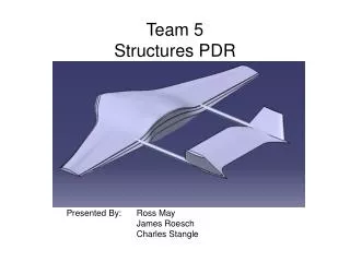
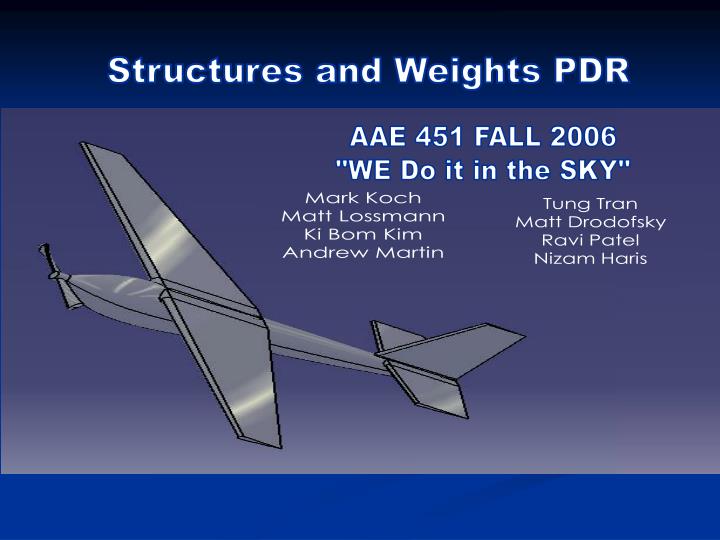
Structures and Weights PDR. AAE 451 FALL 2006 "WE Do it in the SKY". Mark Koch Matt Lossmann Ki Bom Kim Andrew Martin. Tung Tran Matt Drodofsky Ravi Patel Nizam Haris. Over view. Landing Gear Weight Determination Geometric Layout of Wing Structure Analysis of Wing Loads

E N D
Structures and Weights PDR AAE 451 FALL 2006 "WE Do it in the SKY" Mark Koch Matt Lossmann Ki Bom Kim Andrew Martin Tung Tran Matt Drodofsky Ravi Patel Nizam Haris
Over view • Landing Gear • Weight Determination • Geometric Layout of Wing Structure • Analysis of Wing Loads • Fuselage and Tail Structure
Front Landing Gear Material: carbon fiber 8" wide, 5" tall,1-5/8" wide at top, 1" at bottom, 1.5 oz. weight. Main Wheel Diameter: 2-1/16" Steerable Tail Landing Gear 2-3/4" x 3" with 7/8" Plain Wheel Landing Gear
Landing Gear Analysis • Assumptions: • Main Landing Wheels support 90% of weights. • Taildragger aft tires are about a quarter to a third the size of the main tires. • Tire sizing: Diameter : 1.96 in Width: 0.9 in
Tip-over Analysis • Logitudinal tip-over analysis • α & β should be between 16 to 25 degrees. • γ should be between 10 to 15 degrees • Lateral tip over analysis. • θ should be bigger than 25 degrees. α β γ θ
Weight Determination • Center of gravity Y x Center of gravity Moment of inertia (results from CATIA)
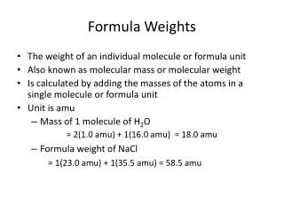
List of Components Total Weight: 5.0074 lb (excluding control wire, hinge and glue)
Layout of Components Receiver Gyro Servos (Rudder Elevator) Speed controller Payload Battery Motor
Material Properties of Wing Structure • Density of Composite • 50% Epoxy + 50% E-Glass • Density of Balsa wood • 0.005 (lb/in^3) • Density of foam • 0.0011(lb/in^3)
Skin & Material • GRP (Glass Reinforced plastic) wing covering (fiber glass w/ epoxy) 3oz E Glass Satin WeaveThickness: 0.0046“ (Two layer 0.0092’’) Epoxy hardener (205(fast) +206(slow)) Epoxy Resin (105)
Wing Assembly Wing Mount + Foam wing Wing Mount Complete wing assembly with fiberglass cover
V-n Diagram Positive Structural Limit Positive Stall Limit q Limit Negative Stall Limit Negative Structural Limit
Bending Moment Maximum bending loads
Wing Tip Vertical Deflection Vertical deflection of wing tip 0.21 (in)
Analysis of wing load Torsion Twist angle = 1(degree) (Area at the tip) (Shear modulus of fiber glass) (Torque) (Required thickness of fiber glass over the airfoil)
Skin Materials Trade Study Purpose: To compare weight of skin made of different materials Method: Single cell Thin-walled analysis Result: Fiber glass has lowest weight
Fuselage Structure • Frame material is wood • Fuselage body material (foam) Interior layout Fully loaded fuselage
Tail Wing Structure • Tail wing dimensions • Materials: • Wood • Foam • Fiberglass • Tail wing assembly