Download
1 / 20
200 likes | 205 Views
Authors:. Overview of proposed LC-optimized PHY. Date: 2019-09-17. Abstract. This contribution presents a summary of new features of the proposed LC-optimized PHY for TGbb . Introduction Adaptive bitloading Distributed MIMO Higher bandwidth Easy implementation

E N D
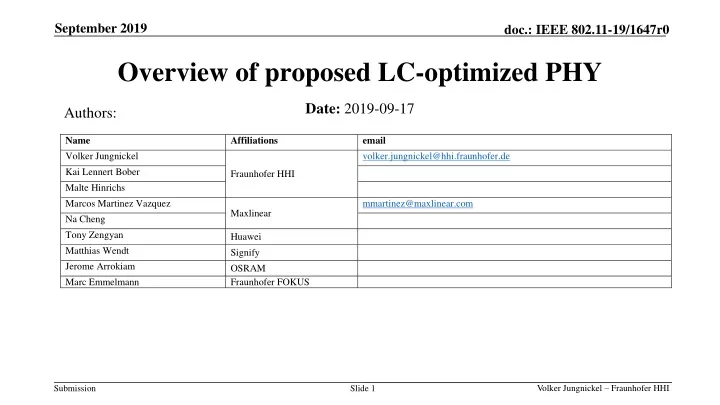
Authors: Overview of proposed LC-optimized PHY Date:2019-09-17
Abstract • This contribution presents a summary of new features of the proposed LC-optimized PHY for TGbb. • Introduction • Adaptive bitloading • Distributed MIMO • Higher bandwidth • Easy implementation • Integration of 11ax with LC-optimized PHY
1. Introduction: How 802.11 RF PHYs work • Bit-interleaved coded modulation (BICM) is the concept behind all existing 802.11 PHYs. • In RF channels, BICM works well. • BICM creates redundancy. Then it permutes bits randomly over all the subcarriers. • In a rare fading event, lost bits can be repaired by the soft-decision FEC. RF
Limitations of 11ax for LC • Limitations of 11ax for LC • Adaptive bitloading is not supported • Bandwidth is limited to 160 MHz • MIMO is limited to 8x8 • New interface to LC frontend is needed • LC should not be limited by 802.11 PHY developed for RF • Light is a new wireless medium • Short-range, more directive, bidirectional, networked, less interfered • LC needs a dedicated PHY to overcome the limitations of 11ax.
2. Why adaptive bitloading? LC • LC channel may be 1storder low-pass, due to • NLOS propagation [1] • Low-power LED driver characteristics [13] • Assume 100 MHz baseband and 20 MHz cut-off due to LED driver or channel • 80% of the bits fall in a fade. • BICM operation will basically fail. Replace BICM by adaptive bitloading. doc. 19-1208r0
Results • See simulation results for adaptive bitloading in 11-19/1566r2. 11-19-1566-02-00bb-simulation-results-with-bit-loading-for-the-lc-optimized-phy.pptx
3. Why distributed MIMO? • LC is envisioned as a dense network • One LC frontend covers few meters spot area • Classical handover concepts are obsolete, taking realistic mobility into account • Centralized AP, distributed LC frontends serve LC Non-AP STAs • Large distributed multiuser MIMO • STAs communicate with a subset of frontends • LC and RF APs could be co-located • RF to provide coverage, LC to add capacity LC AP Fronthaul LC frontend LC Non-AP STA
[2] [2] Kai Lennert Bober, „Performance Evaluation of a Coordinated Visible Light Communication Network“, Master Thesis, TU Berlin, Germany, 2018
Withdistributed MIMO, blind spotsforcommunicationalmostdisappear! • Distributed MIMO enablesconsistent system-level performancefor LC, similartowhatisintuitivelyexpectedfromtheilluminationlevel.
MIMO CE symbols PHY header HCS Preamble CE symbols PSDU How LC-optimized PHY supports distributed MIMO? PHY payload SHR PHR • LC-optimized PHY adds frequency-multiplexed pilot symbols in optional fields, see doc. 11-19-1053-02-00bb-lc-optimized-phy-proposal-for-tgbb.pptx • SISO = single-input single-output • MIMO = multiple-input multiple-output • SHR = Synchronizationheader • CE = Channel estimation • PHR = Physicallayerheader • HCS = Header check sequence • PSDU = PLCP Service Data Unit • PLCP = Physicallayerconvergenceprotocol SISO optional MIMO
Frequency-time multiplexed MIMO RS • MIMO RS use a comb of equally-spaced subcarriers. • A cyclic shift in the frequency domain identifies each LED. One comb is reserved for noise estimation. • The channel is interpolated between non-zero subcarriers, see [11] in doc. 11-19/1053r2. • Classical frequency reuse schemes can be applied for pilot assignments to LEDs.
4. Why higher bandwidth? • SoALC uses high-power LEDs • 1-10 MHz bandwidth, due to large area • LED bandwidth can be improved by • Using infrared as opposed to white LEDs • Sophisticated LED driver designs: High bandwidth needs more energy • Vertical cavity lasers (VCSELs) are widely used in cell phones. • VCSELs have higher bandwidth due to stimulated emission: 1 GHz and more • VCSEL arrays offer it altogether: High power, high bandwidth and low power doc. 11-19/0916r1
How LC-optimized PHY enables higher bandwidth? • LC-optimized PHY is based on the home networking standard G.hn. • G.hn uses one silicon for multiple media: Powerline, phoneline, coax and plastic optical fiber (POF). • For the new LC standard G.9991 the coax profile in G.9960 has been selected.. • The coax profile makes scaling to higher bandwidth straight forward, through the use of carrier aggregation. The concept is under discussion in G.hn2 project. 200 MHz 200 MHz 200 MHz 200 MHz 200 MHz frequency
5. Why implementation is so easy? • LC modulation starts at DC up to some maximum frequency. • LC needs a real-valued baseband signal. • Fixed (incl. home) networking media are very similar. • Baseband chips can be easily reused for LC. data • Reusing baseband signals from RF is much more difficult, see e.g. 802.11ax. • RF has complex-valued baseband up-converted in the same chip to an RF carrier. • New external interface is needed for reusing RF baseband signals for LC. LED/VCSEL LC-optimizedbasebandchip LC frontend AFE chip PD
Easy implementation • Feasibilityisprovenbyseveralproductsfromat least 3 independentvendorsin currentmarketusingthe LC-optimized PHY. • Forexample, see • doc. 11-19-1208-00-00bb • https://www.youtube.com/watch?v=066jgai1Fbc
6. Integration with 11ax • Switching between PHY modes is common practice in 802.11 MAC • It needs a simple common-mode PHY, should support low complexity&energy • This way we can do all the signaling to switch to any more complex PHY
Ressources and references • References and resources for LC-optimized PHY are outlined in doc.11-19-1359-01-00bb-lc-optimized-phy-resources.pptx