Download
1 / 27
270 likes | 470 Views
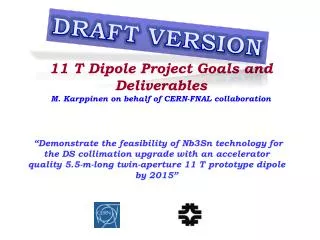
CERN-FNAL Video Meeting #12 Progress of the 11T Dipole short model program (Task 2 of HL-LHC WP-11). CERN MBHSM0101 general status F. Savary on behalf of the 11T Dipole Project Team. Contributions.

E N D
CERN-FNAL Video Meeting #12Progress of the 11T Dipole short model program (Task 2 of HL-LHC WP-11) CERN MBHSM0101 general status F. Savary on behalf of the 11T Dipole Project Team
Contributions • Bateman R.1, Batts S. 1, Bourcey N., Cote D., Duret M., Fernandes C., Izquierdo Bermudez S., Gauthier R., Guinchard M., Grand-Clement L., Grosclaude P., Grospelier E., Jokinen A. 1, Juchno M., Julien V., Karppinen M., Lackner F., Lambert L., Löffler C., Lyon T.-J., Mazet J., Peray N., Pincot F.-O., Savary F., Schmid N., Smekens D., Willering G. • 1Oxford Instrument
Main design features • Single aperture, 6-bloc design • 56 turns • 22 on IL (4 blocs) • 34 on OL (2 blocs) • Aperture: 60 mm • Coil length: 1.8 m • Yoke OD: 510 mm • Shell thickness: 12 mm [AISI 304L]
Specific features • Copper coil #101 • End spacers CERN v0, longer coil • Sc coil #105 • Cable OST RRP 108/127 • ODS alloy wedges • CERN V4 end spacers SLS (with flex hinge legs) • Metallic saddles and splice blocks • External trace, glued on coil OD, carrying V-taps and quench heaters (next slide) • Collars and yoke laminations produced by EDM • Collars YUS130S Nippon Steel 3 mm thickness (LHC dipole) • Yoke laminations ArcelorMagnetil Low C steel 5.8 mm thickness (LHC dipole)
Assembly conditions - Winding D. Smekens J. Mazet • Winding tension: • Coil #101: 300 N; insulation defects: >1 • Coil #105: 250 N; insulation defects: 0 • Cable insulation • Coils #101 and #105: • Outer sleeve: AGY S-2 Glass 11 Tex, direct braiding • Inner dielectric: CogebiFirox 80 µm Mica – Fiber glass tape • Winding monitoring during coil #105 production Coils longer than expected: ~20 mm
Binder curing D. Smekens J. Mazet • Binder CTD 1202-X; qty: • Coil #101 IL: in excess; OL: in excess; • Coil #105 IL: 100 g; OL: 100 g; • Shimming: nominal (shimming such that in the press the mid-plane of the cured coil is like in the magnet; 0.12 mm above center axis) • This is different compared to FERMILAB where oversized shimming is used to compact the coil mid-plane beyond its nominal position in order to obtain a smaller coil size before entering into reaction • With a load of 0.8 MN, the mold is nearly closed (< 0.1mm) • Then, a load of 2 MN is used for IL, and 4.2 MN for the OL (complete pole) • The stress in the coils may not exceed 37 MPa at that stage
Reaction treatment D. Smekens N. Bourcey F. Lackner • Cavity of the reaction fixture is radially bigger than the curing mold by 0.1 mm; and of similar dimension at coil mid-plane • Thus, if the curing press can be closed before reaching 37 MPa, the coil cannot be subjected to higher stress when closing the fixture. However, the dry fiber glass, and the tight tolerances induce large friction; also, a possible dimensional problem with the sealing foils could have generated interference between the sealing foil and the baseplate, preventing correct closure of the fixture • The tightening torque to close the fixture was of the order of 300 Nm (FNAL applies 110 Nm to 160 Nm) • Not clear: no coil contraction after reaction, actually less that 1 mm, when 4.5 mm were expected
Reaction treatment – Coil 105 Adjustment of dwell time to compensate the delay between the temperature and tooling temperature The homogeneity of T during ramp up was not very good, ± 9°C. However, it is OK during dwell time N. Bourcey F. Lackner
Impregnation R. Gauthier D. Smekens • Resin: CTD 101K • Anhydride cured epoxy system with excellent performance at cryogenic temperature, and radiation resistance • The resin is preheated, and the coil is impregnated at 60°C • Curing @ 110°C for 5 hours • Post curing heating @ 125°C for 16 hours
EES5OO EE5O12 EES5OI - EE5O8 EE5O6 EE5O5 EE5O7 EE5O1 EE5O2 EE5O4 EE5O3 EE5O9 + EE5O10 EE5O11 Instrumentation outer layer Outer layer instrumentation incorporated in a Trace which is applied after impregnation. There are 2 “U” shaped SS quench heaters with Cu overlay with Cu masked off to provide heating regions. Heater width is 19mm in low-field region with heater regions 90mm apart. In the high-field region the heater width is 24mm and the heater regions are 130mm apart. There are 13 voltage taps on the Trace, including 6 on the pole turn, 1 on the layer jump and 4 on the mid-plane turn.
Instrumentation inner layer Inner layer instrumentation consists only of voltage taps. There are 16 voltage taps including 6 on the pole turn, 1 on the layer jump and 4 on the mid-plane turn with other taps adjacent to spacer block edges. S. Izquierdo Bermudez F.-O. Pincot R. Bateman
Quench heaters Cu Cu 19/24 50 90/130 • Width -> Cover as many turns as possible • LF: 19 mm • HF: 24 mm • Power density • LF ≈ 75 W/cm2 • HF≈ 55 W/cm2 Heater width: 19 mm LF, 24 mm HF ρss=7.3·10-7Ωm, RRR=1.34 Operation area Even if the operational current is expected to be in the range 100-120 A, it would be good to have the possibility to go up to 150 A during short model tests to check the saturation of the system in terms of heater delays • Distance between heater stations -> quench propagation in between stations ≈ 5 ms • LF: 90 mm • HF: 130 mm • Coverage: maximum coverage keeping the resistance within the allowable limits for a 5.5 m magnet (depends on the number of power supplies/heater circuits)
Coils size • Both coils, 101 and 105, were oversized, only in the mid-plane • Best-fit on the outer diameter and the loading plates (interface with pole)
Collaring steps With 8MN the stoppers of the collaring tool were in contact
Shimming plan • Mid-plane is 650 µm beyond expectations. To compensate: • One layer of Kapton was removed on the mid-plane • Changed one layer of insulation to 0.05 µm thickness (in lieu of 0.125 µm)
Yoking / welding of the shells F. Lackner Max. charge: 500 t/m on central section to close the welding gap
ANSYS Forecast at 11-Tesla Coil Blocks Azimuthal Stress At 11T Collar Nose Von-Mises Stress At 11T FEA predicted results
Bullet gauges loading M. Guinchard P. Grosclaude 8 to 9 kN per bullet
Electrical tests – When? F.-O. Pincot L. Grand Clément Are performed before/after each important construction step • Test of pole : Nb3Sn, before curing - PBC • Test of pole : Nb3Sn, before reaction – PBR • Test of pole : Nb3Sn, after reaction – PAR • Test of pole : Nb3Sn, after impregnation out of the mould – PAI • Test of pole : Nb3Sn, after impregnation with instrumentation – PAIWI • Test of collared coil before collaring – BC • Test of collared coil after collaring – AC • Test of the magnet under load before welding – UL • Test of the magnet after shell welding – AW • Test of the magnet after longitudinal coil loading – AL • Test of the magnet after interconnection – AI • Final Test of the magnet before delivery - FINAL
Electrical tests – What? F.-O. Pincot L. Grand Clément According to the construction step, we define: specific test values electrical tests, among which • Resistance measurement (Coils, Quench heaters, Voltage taps, Instrumentation) • Inductance measurement • Capacitance measurement • Dielectric measurement (between coils / QH / instrumentation / ground) • Insulation (up to 1kV; 30s) • current leakage (up to 1kV; 5min) • Discharge test on coil Up to 1kV • Discharge test on quench heaters Up to 900V or 80A/QH
Electrical tests F.-O. Pincot L. Grand Clément
Plan for power tests @ cold G. Willering • Cool down • Day 1 • Day 2-4 • Day 5-7 • Day 8 • Day 9-11 • Day 12-14 • RRR and strain gauge measurements • Preliminary tests – Setup protection – Splice resistance measurements (current plateaus at 2, 4, 6, 8 and 10 kA) – 3 hours • Training 4.3 K – 15 quenches?? – 3 days ?? • Training 1.9 K – 10 quenches?? – 2.5 days??Stability on current plateau – 0.5 day • Ramp-rate study 100 A/s and 50 A/s – 0.5 dayAC-loss measurements (includes inductance measurement) at 5 to 100 A/s – 0.5 day • Quench heater efficiency study: 3 different settings of QH pulse for 3 currents each. Long re-cooling of the magnet due to delay of energy extraction – 3 days • High MIIts tests (protection delay) 6 quenches – 3 days • Quench propagation velocity measurements: acquired for the training quenches.
Further actions • After cold tests, warm magnetic measurements will be carried out, with the two coils connected • Model #1, MBHSP101, single aperture, with cable OST RRP 108/127 for both poles • Instrumentation of coils 106 and 107 going on • Collaring scheduled around middle of June