Download
1 / 13
140 likes | 338 Views
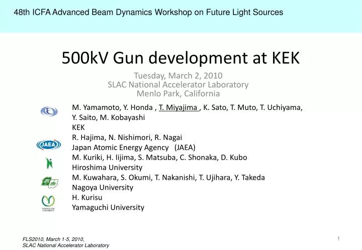
48th ICFA Advanced Beam Dynamics Workshop on Future Light Sources. Tuesday, March 2, 2010 SLAC National Accelerator Laboratory Menlo Park, California . 500kV Gun development at KEK. M. Yamamoto, Y. Honda , T. Miyajima , K. Sato, T. Muto, T. Uchiyama, Y. Saito, M. Kobayashi KEK

E N D
48th ICFA Advanced Beam Dynamics Workshop on Future Light Sources Tuesday, March 2, 2010SLAC National Accelerator LaboratoryMenlo Park, California 500kV Gun development at KEK M. Yamamoto, Y. Honda , T. Miyajima , K. Sato, T. Muto, T. Uchiyama, Y. Saito, M. Kobayashi KEK R. Hajima, N. Nishimori, R. Nagai Japan Atomic Energy Agency(JAEA) M. Kuriki, H. Iijima, S. Matsuba, C. Shonaka, D. Kubo Hiroshima University M. Kuwahara, S. Okumi, T. Nakanishi, T. Ujihara, Y. Takeda Nagoya University H. Kurisu Yamaguchi University
Introduction Gun development Gun Cathode preparation system Laser development Summary Outline
Compact ERL (test facility) Principal parameters Conceptual design report: KEK Report 2007-7/JAEA-Research 2008-032 * With some emittance growth due to CSR
Reason why two 500kV DC guns develop • There are a lot of development elements of the • 500kV DC gun. • - Insulator breaking (punch-through problem) • - Extreme high vacuum (<1E-10Pa) • - Dark current from electrodes • (<10nA@E~10MV/m) • The gun system for R&D machine is • indispensable to establish a technology of high • beam current operation of ~100mA. • For a backup when a serious damage is • occurred in installed gun system while operation. JAEA 1st Gun KEK 2nd Gun
2nd 500kV gun system concept • Using titanium for the chamber and flanges to decrease outgassing rate. • H. Kurisu et al.,“Titanium alloy material with very low outgassing”, J. Vac. Sci. Technol. A21 (2003) L10 • Design that enables easy maintenance, considers extendibility and compatibility with the 1st 500kV gun. • - Two ceramic tube structure, large maintenance • port, compatible flange structure are employed. • - A more large-scale ceramic tube can be connected • by a part of remodeling. • Using a specialized pumping system forextreme high vacuum. • - Combination of NEG pumps and a bakeable cryopump. • H. Yamakawa , “Development and performance of bakeable cryopumps for extreme high vacuum”, Vacuum 44 (1993) 675. • Decreases cathode preparation duty. • - Using a multiple cathode preparation system.
< 10-10 Pa 10-10 Pa Cs & O2 Atomic H 10-9 Pa 10-8 Pa 2nd 500kV gun system Stock chamber Multiple activated photocathode preservations Gun chamber Long-term gun operation is guaranteed by multiple puck system. Installation of Puck Quick exchanges of Puck Activation Chamber Valve Transfer line Loading Chamber Multiple NEA-surfaces are formed simultaneously. Multiple cathode cleaning by atomic hydrogen Puck revolver
Design of the 2nd 500kV Gun Loading chamber (SUS) Ceramic insulators Stock chamber (Titanium) e- beam Bakeable cryopump connection Activation chamber (SUS) Gun Chamber (Titanium) NEG pump connection
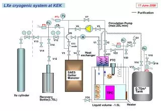
Vacuum system < 10-10 Pa 10-10 Pa Gun chamber (Ti+CP) NEG pump: ~10m3/s (max. ~25m3/s) Bakeable cryopump: 3m3/s for H2 @1E-7Pa (TMP: ~1m3/s for baking) 10-8 Pa 10-9 Pa Stock Chamber (Ti+CP) Activation Chamber (SUS+CP) Loading Chamber (SUS+CP) NEG pump: 1.6m3/s Ion pump: 0.1m3/s NEG pump: 0.8m3/s Ion pump: 0.2m3/s Vacuum gauges for XHV ・AT gauge ・Bent Belt Beam (3B) Gauge Ion pump: 0.1m3/s (TMP: 0.3m3/s for baking, cleaning process)
Design and fabrication (5.Feb) Titanium chamber(12.Feb)
Photocathode DC Gun Test Facility at KEK PF-AR south experiment area Laser room Future layout Laser system 200kV Gun 2nd 500kV Gun construction area Evaluation of cathode, beam control and monitor system by 200kV gun system. 200kV Gun 2nd 500kV Gun
Laser system for injector commissioning at KEK • Drive laser for AR-south injector commisioning test area (started since 2009) • Requirement for 10mA operation of cERL: 1.3GHz(repetition), 530nm(wavelength), 20ps(pulse duration), 1.5W(power) • System has been built based on commercial units (1.3GHz oscillator, fiber amplifier, SHG, etc.) • 100mW (2ω) output has been achieved. Enough for first commisioning of the injector upto 1mA. Development of higher power amplifier is on going. 1.3GHz oscillator pulse compressor pre-amplifier 10W-amplifier (30W-amplifier) pulse train shaping Second Harmonics transport , shaping
Laser system for injector commissioning at KEK • Pulse train shaping (pulse train of 1000 bunches) has been introduced for burst operational mode. This is for commissioning phase of ERL operation. • In order to test high bunch charge beam, lower rep.rate higher intensity Ti:sapphire laser system will be used. • Laser transport line and input chamber are made. laser input chamber burst mode operation
Summary • 2nd 500kV gun development • Design of the gun chamber, the insulators, and the preparation chambers were finished. • Bakeable cryopump is employed for the gun. • Vacuum test will be started at April 2010. • Design of the multiple cathode preparation system is progressed. • Laser system • Development of 1.3GHz fiber laser system for 1mA beam commissioning is almost reach the target. • Development of higher power amplifier is on going.