Download
1 / 22
220 likes | 333 Views
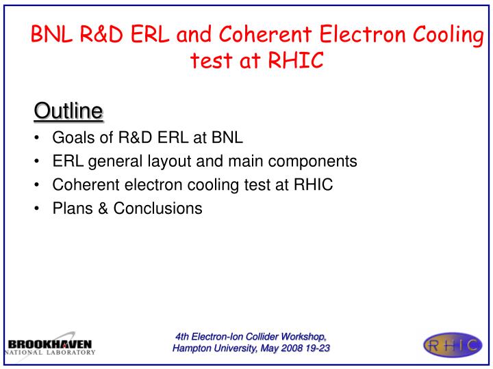
BNL R&D ERL and Coherent Electron Cooling test at RHIC. Outline Goals of R&D ERL at BNL ERL general layout and main components Coherent electron cooling test at RHIC Plans & Conclusions. e-cooling (RHIC II). PHENIX. Main ERL (3.9 GeV per pass). STAR. e + storage ring

E N D
BNL R&D ERL and Coherent Electron Cooling test at RHIC • Outline • Goals of R&D ERL at BNL • ERL general layout and main components • Coherent electron cooling test at RHIC • Plans & Conclusions 4th Electron-Ion Collider Workshop, Hampton University, May 2008 19-23
e-cooling (RHIC II) PHENIX Main ERL (3.9 GeV per pass) STAR e+ storage ring 5 GeV - 1/4 RHIC circumference Four e-beam passes Introduction • R&D ERL will serve as a test-bed for future RHIC projects: • ERL-based electron cooling (conventional or coherent), • 10-to-20 GeV ERL for lepton-ion collider eRHIC. • It will also address general issues expanding capabilities of ERLs: • novel SRF injector, • high current and high brightness beam ERL operation, • flexible lattice to enable covering a vast operational parameter space. 4th Electron-Ion Collider Workshop, Hampton University, May 2008 19-23
Goals for ERL R&D at BNL • Test the key components of the High Current Energy Recovery Linac based solely on SRF technology • 703.75 MHz SRF gun test with 500 mA • high current 5-cell SRF linac test with HOM absorbers • Single turn - 500 mA • test the beam current stability criteria for CW beam currents • Demonstrate beam quality close to that required for high energy electron cooling • Test the attainable ranges of electron beam parameters in SRF ERL 4th Electron-Ion Collider Workshop, Hampton University, May 2008 19-23
Cryo-module Beam dump e- 2.5 MeV SRF cavity 1 MW 703.75 MHz Klystron Schematic Layout of the ERL e- 15-20 MeV Return loop Laser Cryo-module Merger system e- 2.5MeV SC RF Gun 50 kW 703.75 MHz system Control room 4th Electron-Ion Collider Workshop, Hampton University, May 2008 19-23
Half cell SRF Gun fRF= 703.75 MHz Energy=2.5-3 MeV Average Current: 0.5 A Two fundamental power couplers: 0.5 MW each A. M. M. Todd et al., “State-of-the-Art Electron Guns and Injector Designs for Energy Recovery Linacs”,PAC2005 SC RF Gun: shape and axial electric field profile (SUPERFISH result) Electron beam energy gain at the exit of the gun versus initial phase SC RF Gun: axial electric field profile for different cathode insertion depth (SUPERFISH result) 4th Electron-Ion Collider Workshop, Hampton University, May 2008 19-23
ERL Loop Dipole SRF Gun SRFLinac Z-merger Dipoles Solenoids BNL R&D ERL SRF Injector layout 4th Electron-Ion Collider Workshop, Hampton University, May 2008 19-23
BNL ERL Injector: beam dynamics simulation results 30º 70 cm 15º 99.5 cm 70 cm -15º 5 cell SC RF cavity SC RF Gun -30º Horizontal Vertical Evolution of normalized beam emittances in the BNL R&D ERL injector Blue 5 nC Red 1.4 nC Green 0.7 nC 4.8/5.3 um 2.2/2.3 um 1.4/1.4um 4th Electron-Ion Collider Workshop, Hampton University, May 2008 19-23
ERL: loop layout 20 MeV Beam dump SC RF Gun SC 5 Cell cavity 2-3 MeV 20 MeV 2-3 MeV 2-3 MeV 20 MeV Modes of operationCritical parameters High energy acceptance Low dispersion, large aperture Beam break up instability study Adjustable transverse phase advance Longitudinal motion study Adjustable longitudinal dispersion Two pass acceleration Changeable path length 4th Electron-Ion Collider Workshop, Hampton University, May 2008 19-23
ERL loop lattice is very flexible Lattice and D functions of the ERL for the different cases longitudinal dispersions (Ds=M56): No dispersion b, m Dispersion, m Positive longitudinal dispersion Zero longitudinal dispersion Negative longitudinal dispersion Transverse normalized emittances from cathode to dump Q=0.7 nC (PARMELA simulation) 4th Electron-Ion Collider Workshop, Hampton University, May 2008 19-23
BNL 5 Cell SRF Cavity Design F = 703.75 MHz, E = 20 MeV Q0~ 1010, QHOM ~ 103 • The 5-cell cavity was specifically designed for • high current, high bunch charge applications such as eRHIC and high energy electron cooling. • The loss factor of the cavity was minimized. • The number of cells was limited to 5 to avoid HOM trapping. • Additionally, HOM power is effectively evacuated from the cavity via an enlarged beam pipe piece 24 cm diameter. Build: AES Processed: JLAB Arrived at BNL 4th Electron-Ion Collider Workshop, Hampton University, May 2008 19-23
Cavity VTA tests The cavity was processed at JLab. After BCP, Rinsing, and low temp. bake (120 C) cavity reached 19 MeV/m at Q0=1010. 19 MeV/m Ebeam,max 20 MeV 4th Electron-Ion Collider Workshop, Hampton University, May 2008 19-23
HOM measurements The simulated BBU threshold is of the order of 20 A for the nominal designed ERL lattice and simulated HOM parameters. GBBU and TDBBU codes were used. Several dipole modes at frequencies below 1 GHz were measured and could be identified by comparison with simulation results The damping of the Q-values is 2 orders of magnitude. Results well agree with simulations. 4th Electron-Ion Collider Workshop, Hampton University, May 2008 19-23
R&D ERL beam parameters Operation regime Parameter 4th Electron-Ion Collider Workshop, Hampton University, May 2008 19-23
20 MeV Beam dump SC RF Gun SC 5 Cell cavity 2-3 MeV 20 MeV 2-3 MeV 2-3 MeV 20 MeV BNL R&D ERL: Status Quadrupole Dipole • ERL Enclosure (Vault) was constructed • 5-cell Cavity is being processed and tested at JLAB, arrived in March, 2008 • The dumping of HOM Q-values measured 2 orders of magnitude • 1 MW Gun klystron and 50 kW 5-cell cavity transmitter are installed • Recirculation loop magnets and vacuum system components have arrived • Injection dipoles are under magnetic measurements • Gun drive laser is been procured • Gun is under construction at AES BPM Measured, ready to be installed DCCT Arc assembly Arrived, test this summer Tested in BLD912 50 kW Transmitter ready to operate SRF Linac 1MW Klystron 4th Electron-Ion Collider Workshop, Hampton University, May 2008 19-23
R&D ERL Commissioning Milestones and beyond Coherent Electron Cooling Proof of Principal Test around 2012 4th Electron-Ion Collider Workshop, Hampton University, May 2008 19-23
Modifications from R&D ERL to P-o-P CEC • Move SRF Gun, 5cell cavity, loop arcs and injection line from 912 to IR2 Bldg 912 IR2 • Stretch straight line in order to accommodate cooling section (modulator-undulator-kicker ) ~15 m • Build and install 7 m undulator 4th Electron-Ion Collider Workshop, Hampton University, May 2008 19-23
IR-2 for proof-of-principle for CEC 19.6 m SC 5 Cell cavity electron and ion beams 7 m RHIC Beam 4 m RHIC Beam 4 m RHIC lattice functions IR2 4th Electron-Ion Collider Workshop, Hampton University, May 2008 19-23
Electron beam lattice functions for CEC PoP test at RHIC UNDULATOR Kicker region Modulator region 4th Electron-Ion Collider Workshop, Hampton University, May 2008 19-23
BNL R&D ERL electron beam longitudinal profile The electron bunch is +/-15 degrees of RF Q=1.4 nC, 100% : dE/E=4.8x10-3, ex/ey=5.6/6.7 um 80% : dE/E=1.3x10-3, ex/ey=5.4/5.6 um For CEC: emittance requirements are relax The energy spread is important Some injection line modification may be applied 4th Electron-Ion Collider Workshop, Hampton University, May 2008 19-23
CEC proof of principal at RHIC setup Ion bunch parameters Electron bunch parameters 4th Electron-Ion Collider Workshop, Hampton University, May 2008 19-23
CEC proof of principal at RHIC setup (cont.) Cooling parameters FEL parameters Electron bunches are usually much shorter that the hadron bunches and cooling time for the entire bunch is proportional to the bunch-lengths ratios Ion bunch: 2.5E-09 sec Electron bunch: 50E-12 sec The formula gives very encouraged result More simulations and accurate studies are under way 4th Electron-Ion Collider Workshop, Hampton University, May 2008 19-23
Plans & Conclusions • Design of major ERL components is completed. Hardware components are being manufactured and/or procured. • We plan to start commissioning of the R&D ERL in 2009 • First, we develop the straight pass (gun -- 5 cell cavity -- beam stop) test for the SRF Gun performance studies. • Next, a novel concept of emittance preservation in a beam merger at the lower energy will be tested • After recirculation loop completed, demonstrate energy recovery of high charge and high current beam • The prototype will serve as a test bed for studying issues relevant for very high current ERLs(since 2010) • Proof of principle coherent electron cooling ions in RHIC at ~ 40 GeV/n is feasible with existing R&D ERL parameter and should be demonstrate around2012 4th Electron-Ion Collider Workshop, Hampton University, May 2008 19-23