Download
1 / 25
250 likes | 520 Views
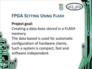
FPGA-Based Test Platform for Flash Error Mechanism Investigation. Yu Cai Erich Haratsch. Outline. Background Hardware Architecture Implementation Future Work. Current NAND Flash Challenges. NAND Flash memories are widely used for data storage (USB Flash drives, SSDs)

E N D
FPGA-Based Test Platform for Flash Error Mechanism Investigation Yu Cai Erich Haratsch
Outline • Background • Hardware Architecture • Implementation • Future Work
Current NAND Flash Challenges • NAND Flash memories are widely used for data storage (USB Flash drives, SSDs) • Compactness, low power, high throughput and low cost • Doubling of NAND Flash density each year through production geometries shrinking and SLC to MLC migration makes reliability a critical issue • NAND’s Physical Impairments: Cross coupling, read/write disturbs, data retention etc • Current Error Correction Code (ECC) itself is becoming insufficient to retain reliability in NAND-based products
Future NAND Controller Architecture Raw Bit Error Rate Error Correction BER < 10-15 Signal Processing • BCH Codes • Reed-Solomon • Binary-LDPC • Non-binary-LDPC Low Cost/Bit High Area Density More Noises/Errors Challenges: Unknown NAND Flash Error/Noise Patterns
Error Patterns Generation Erase Program Read Compare Millions of Times Error Patterns Generated
System Architecture Algorithms Wear Leveling Address Mapping Garbage Collection ECC (BCH, RS, LDPC) Control Firmware Signal Processing Software Platform USB PHYChip FPGA (Data Pipe) NAND Controller Flash Memories USB Driver Host USB PHY Host Computer USB Daughter Board Mother Board Flash Board
USB Daughter Board USB Jack HAPS-52 Mother Board Virtex-II Pro (Data Pipe) NAND Daughter Board Flash Emulation Platform Virtex-V FPGA (NAND Controller) NAND Flash
USB Daughter Board USB Jack USB PHY Chip HAPS Interface Virtex-II Pro FPGA
USB Daughter Board Logic Design FPGA Virtex-II Pro (Master Logic) Control CPU (Enhanced 8051)
USB Interface Implementation • Software • Windows Application Software • Send/Receive USB Packet, Command Interface • Cypress USB driver • Firmware • Cypress USB Firmware on Enhanced 8051 • USB behavior configuration, Interrupt routine processing • RTL Logic • Glue logic in Virtex-II Pro as data pipe between USB PHY chip and NAND controller
Experimental NAND Flash Features HAPS Interface Flash Chips • TSOP Package, ONFI compliant • Single-Level Cell (SLC) Technology • Organization • Page Size x8: 4314 Bytes (4096 + 128) • Block Size: 64 Pages (256K + 13K Bytes) • Plane Size 8Gb: 4096 blocks • Read Performance • Random Read: 25 us • Sequential Read: 25 ns • Write Performance • Program Page: 250 us • Block Erase: 700 us • Endurance • 100,000 Program/Erase Cycles (4-bit ECC)
NAND Controller HAPS Interface NAND Controller Finite State Machine 8x Write Page Buffer Flash 1 8x Flash 2 Control Register Files Error Pattern Generation Accelerator 8x Flash 3 8x Read Page Buffer Flash 4
NAND Controller Implementation Reset NAND Read ID Read Status Start Read Page Erase Block Program Page
Sample NAND Flash Pin Assignment Timing Signals CE: Chip Enable CLE: Command Latch Enable RE: Read Enable R/B: Ready/Busy ALE: Address Latch Enable WE: Write Enable
NAND Flash Reset Command Timing Specification Chip-Scope Results
Erase Block Command Timing Specification Chip-Scope Results Long Erase Time (tBERS)
Read Page Command Timing (Example) Specification Chip-Scope Results Correct! All FF after Block Erase
Read Status Command Timing Specification Chip-Scope Results E0 Means Correct Erase Status No Write Protect Ready/Busy Successful Program/Erase
Program Page Command Timing Specification Chip-Scope Results
Read ID Command Timing Specification Chip-Scope Results Micron MT29F8G08 8Gb, x8, 3V
Current Status • All sub-modules integrated together • Application C++ code, USB driver, Embedded firmware on 8051, RTL code on Virtex-II Pro (data pipe), RTL code for NAND controller on Virtex-V • Automatic Flash memory testing is now running to collect data • Raw write/read files generated on host machine • Data Pattern: Independent Uniform Random Data • Program Pattern: First four pages of even and odd Blocks • Speed: 200 erase-program-read-compare cycles/hour • Raw data for 4000 write/read cycles generated • Errors not found in the first 4000 cycles, need to run the board for a longer time
Future Work • Short Term • Accelerate the whole system • Generate Error/Noise Patterns for SLC • Long Term • Generate Error/Noise Patterns for MLC • Propose new signal processing and error correction codes • Propose new wear leveling algorithms • Evaluate good algorithms with real hardware implementation • Enhance platform to support highly-parallel computer architecture exploration under NAND Flash clusters (eg. >100 NAND chips) • Enhance platform to investigate wear leveling of NAND flash storage under multi-thread / multi-core processors
Acknowledgement Erich Haratsch Chris Dougherty Jongseung Park Dave Savory Brian Nowak David Smith Peter Calabrese (Synopsys) Other Related LSI employees and interns