Download
1 / 20
210 likes | 513 Views
Low-Energy Linac Upgrade Scenarios. Elliott McCrory BD/Proton/Linac 21 November 2003. Why Another Linac Upgrade?. The supply of 7835 power amplifiers may end soon Ingrid Bergman as Mike Witherell: "You're saying this only to make me [spend money]."

E N D
Low-Energy Linac Upgrade Scenarios Elliott McCrory BD/Proton/Linac 21 November 2003
Why Another Linac Upgrade? • The supply of 7835 power amplifiers may end soon • Ingrid Bergman as Mike Witherell: "You're saying this only to make me [spend money]." • Humphrey Bogart as Elliott: "I'm saying it because it's true. Inside of us, we both know [Burle will go out of business someday]. If that [happens] and you're not [prepared], you'll regret it - maybe not today, maybe not tomorrow, but soon, and for the rest of your life." • Modulator “switch tubes” are no longer available • We have a 5-10 year supply of these tube • Activation in the Linac may become a problem • Matching between 201 MHz and 805 MHz portions is not ideal • #particles/day is 6X higher in FY03 than FY00 • And MiniBooNE and NUMI want ~4X more than this • Many 33-year-old components are difficult & expensive to maintain • LEL Quad Power supplies ($1M to replace, ASAP) • LEL LLRF, driver amplifiers, etc., etc. • Technical staff that built LEL are nearing retirement Elliott McCrory
Linac Upgrade Possibilities • Replace the Cockcroft-Walton & prototype tank 1 with a 201 MHz RFQ to 10 MeV • But only solves the activation issue • Replace the 201 MHz portion of the Linac with a 402 MHz Linac • Solves all issues • Similar to SNS • Several possible scenarios • Add more accelerating modules at the end • Solves no issues, but would help Booster • Conventional SCC modules, like existing Module 7, or … • Superconducting modules, similar (identical?) to 8 GeV Linac injector Elliott McCrory
New 402 MHz Low-Energy Linac • Original: Don Young, “PD Study 1” (2002) • Commercial partner • AccSys Technologies, Pleasanton, CA • 80% owned by Hitachi • Potential collaborations with: • New Proton Driver efforts • Foster and/or Chou • Fermilab’s NTF (Arlene Lennox) • “Fermi Institute of Hadron Therapy” • $50M from Hastert?! • National Taiwan University Hospital, Hsinchu Biomedical Science Park • Taipei, Taiwan • Has ~$100M ready to spend NOW Elliott McCrory
From AccSys Web page Synchrotron Injector Linac Systems The LINSTAR™ series of proton linac systems are designed to provide moderate-energy proton beams (typically from 2 to 7 MeV) for injection into high energy proton synchrotrons that are used for proton beam cancer therapy or physics research. These fully integrated systems typically consist of a carefully designed and selected combination of a radiofrequency quadrupole (RFQ) linac, a drift tube linac (DTL) for injection energies of >3 MeV, AccSys' standard rf power system, a high energy beam transport system tailored to the specific requirements of the facility and an optional debuncher cavity. They can accelerate either H+ or H- ion beams and are also available for polarized H+ or H- beams. Standard LINSTAR™ units can provide pulsed beam currents up to 25 mA at pulse widths from 3 to 300 µsec. Operation at pulse repetition rates from 0.1 to 30 pulses per second have been demonstrated, including on-demand pulsing for breath-mode synchronization in proton cancer therapy. LINSTAR™ systems are currently in use at several facilities around the world: A Model PL-2i has been operating at Loma Linda University Medical Center since 1990 as the injector to the high energy proton synchrotron cancer treatment facility. The synchrotron system operates 24 hours a day, 6 days a week and has been described in a number of technical publications. Complete proton therapy systems based on the Loma Linda installation are commercially available from Optivus Technology, Inc. Two systems are being commissioned in Japan: a Model PL-3i is the injector to the proton synchrotron cancer treatment facility at the Shizouka Cancer Center, being built by Mitsubishi Electric Company, and a Model PL-7i is the injector for the proton synchrotron cancer treatment facility being installed at the Tsukuba Medical Center by Hitachi, Ltd. A Model PL-7i has been operating at the Indiana University Cyclotron Facility since 1997 as the injector for the CIS compact synchrotron which is in turn the injector for the high energy physics cooler ring. Elliott McCrory
Two Scenarios: Commonalities • Replace Cockroft-Walton with two redundant RFQs • Available from AccSys technologies • 3 MeV • New LEBT • including the “Double Alpha” idea invented by Del Larson • No need for a buncher cavity. • New DTL from 3 to 70 or 89 MeV • Tank 1: Ramped Gradient Drift Tube Linac • RGDTL available from AccSys technologies • Three or four new 402 MHz DTLs • New Transition section • We can “do it right” this time • One or two new SCC modules to 116 MeV • Extra room at 400 MeV to add more acceleration Elliott McCrory
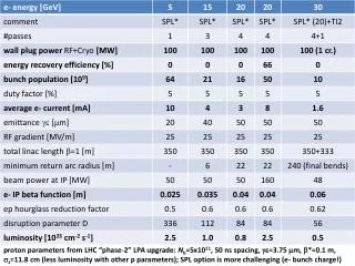
Basic Parameters of Today “SCC” == “Side Coupled Cavity” “LEL” == “Low Energy Linac” Elliott McCrory
Three Scenarios • Modest • 2 RFQ, RGDTL, 4 DTL, 2 LE SCC • Luxury • 2 RFQ, RGDTL, 5 DTL, 1 LE SCC, 2 new modules at 400 MeV • Shift existing SCC modules upstream by ~18 m • More aggressive ideas (not explored here) • 800 MeV?? • Move everything upstream into C-W pit (+ ~ 100m?) • Add Superconducting accelerating cavities at end Elliott McCrory
Schematic Layout of #2 Solid: NEW Hatched: Existing RGDTL DTL Tank 2 DTL Tank 3 DTL Tank 4 DTL Tank 5 RFQ 2 RFQ 1 ~89 MeV […] Trans0 TransV New Module 1 Existing Module 1 To Booster at ~480 MeV Existing Module 7 New Module 8 New Module 9
Benefits of a new LE Linac • Replaces all 33-year-old Linac equipment • SOA technology • NO MORE 7835’s! • Increase beam brightness • Probably: 2 to 4 X smaller transverse emittance • Existing technical staff: Days are numbered • New technical staff can “own” this new machine • New machinery and new people might last another 30+ years • 402 MHz Klystrons exist • And our 805 MHz klystrons last “forever” • Significantly shorter than existing LEL • Could add more modules at the end to give an energy boost • Higher injection energy into Booster is better • Reduced losses/activation throughout the Linac • Transition section is our predominant loss now • Lower emittance would mean lower 400 MeV-line losses Elliott McCrory
Higher Energy Linac Benefits • The space charge limit for constant aperture at Booster injection scales like β2γ3 Elliott McCrory
Pet Project (1996) RFQs Elliott McCrory
Double αMagnet: Del Larson Elliott McCrory
Trace-3D Run of PET MEBT Longitudinal RFQ 1 RFQ 2 Elliott McCrory
From Larson’s ‘96 MEBT paper 6.1. Longitudinal Control. […] some control over the longitudinal phase space can be exercised by using the trim quads located in the cross over arm. The MEBT has been designed to have a high dispersion in this region, and quadrupole variations in this region therefore have a large effect on the dispersion function. The dispersion is introduced in the first alpha magnet, and the magnet and optics have been nominally designed so that the dispersion function has zero gradient in the middle of the cross over arm. With zero dispersion gradient and transverse waists in the center of the cross over arm, the beam will have symmetric optics about this point, leading to zero dispersion and zero dispersion gradient at the end of the second alpha magnet. While the first goal of the trim quads is to ensure a symmetric dispersion function, so as to eliminate dispersion at the end of the MEBT, a second function can be to control the position of the longitudinal waist. Since small trim quad variations have a large effect on the dispersion and a small effect on the transverse beam optics, the longitudinal control exercised by the trim quads is largely independent of the transverse optics. 6.2. Transverse Control. Once dispersion has been minimized (by arranging for symmetric optics within and between the dipoles) the quadrupoles placed downstream of the dipoles will have no effect on the longitudinal optics and can therefore be used solely for transverse optics matching. Since there are three such quads, one can in principle exercise control over three linear combinations of the four independent transverse phase space variables. […] Elliott McCrory
Linac Upgrade Params (#1) Elliott McCrory
Linac Upgrade Params (#2) Elliott McCrory
Rough Cost Estimate Elliott McCrory
Final Thoughts • Collaborators galore! • NTF/Lennox • Taiwan • AccSys (but not for free) • How much longer can we get 7835 power amplifiers? • How much longer can we maintain the old Linac? • The time is right to proceed on this Elliott McCrory