Download

1 / 16
160 likes | 282 Views
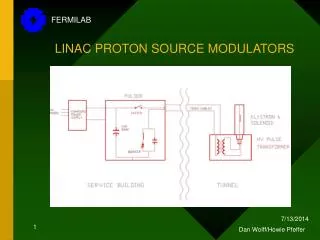
FERMILAB DESIGN Howie Pfeffer /Jim Biggs 12/19/12. LINAC LOW ENERGY MODULATORS status update. Fermilab specs. SOME SPECS Pulse rep rate: 15 Hz Maximum Output: 35 kV Load ~100 ohm Rise time (Adjustable): 150 usec

E N D
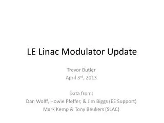
FERMILAB DESIGN Howie Pfeffer/Jim Biggs 12/19/12 LINAC LOW ENERGY MODULATORSstatus update
Fermilab specs SOME SPECS Pulse rep rate: 15 Hz Maximum Output: 35 kV Load ~100 ohm Rise time (Adjustable): 150 usec Fall time (Adjustable): 150 usec Flat top time (Adjustable): 160 usec Beam Length/Time (Adj.): 110 usec Maximum step size: 1.5 Kv SOME OF THE TOUGH SPECS: Beam Top Tilt (Adj.): +/- 5 kV Beam Voltage Step SR: 15 kV/usec Flattop/Beam Regulation: +/- 25 V Repeatability: +/- 10 V Maximum sparkEnergy: < 5 Joules Essentially a 35kV, 350 amp, OPAMP Capable of 15 kV/usec slew rate
Basic Test circuit Snubber Current Generation Circuit
Current with step Current
Igbt 40u.5.6uhi direct Current Collector Volt Emitter Volt
900 volt – gate voltage Collector Volt Gate Volt CT1 Current Gate Control
900 volt, 20 usec Gate Volt Collector Volt CT1 Current CT2 Current
IGBT Switching action has been confirmed with acceptable transient voltages. IGBT short circuit current limiting and safe turn-off have been confirmed for turning on into a short and “spark-type” short circuits. Design for a 10 stage pulser is complete. conclusions
Starting to specify and order parts for 10-stage Expect to have parts ordered by end of January Parts should be here in 3 months Begin mechanical design and layout beginning of February. Future plans