Download
1 / 14
150 likes | 342 Views
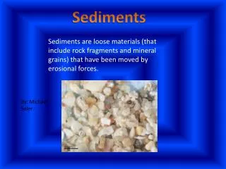
The Structure of Toner Sediments Simulated with Random Ballistic Deposition. Howard Mizes Xerox Corp. October 20th, 1999. Geometric model of toner deposition. Toner arrangement affects Image Quality Subsystem effectiveness Physical Model Focus on dynamics Simulates process of deposition

E N D
The Structure of Toner Sediments Simulated with Random Ballistic Deposition Howard Mizes Xerox Corp. October 20th, 1999
Geometric model of toner deposition • Toner arrangement affects • Image Quality • Subsystem effectiveness • Physical Model • Focus on dynamics • Simulates process of deposition • Geometric model • Focus on structure • Define rules for how toner packs • Calculate packing metrics and relationship to rules vs
Random Sequential Adsorption • Deposition rules • Drop particle from random position • If particle overlaps with another particle, discard. • If particle lands in halftone dot, keep.
Jamming limit • How dense are monolayers? Hexagonal Packing Square Packing RSA coverage = 90.7% coverage = 78.5% coverage = 51.7% • RSA better approximates toner deposition • Maximum coverage at low packing fractions compared to periodic lattices.
Ultimate Graininess • Graininess due to halftone dots changing size randomly. • RSA simulates ultimate graininess achievable with finite sized toner. N=78 N=74 N=78 N=76 • Uniform images can be achieved with 10 mm toner. • (H. Mizes, NIP8)
Random Ballistic Deposition • Drop particles vertically from random position • If particle hits another on way down, then stick to it. • Otherwise, particle hits substrate. • Simulations performed in 3 dimensions
Low density packing fraction • Liquid ink development is the deposition of toner multilayers. • Integrity of image depends on packing fraction. • For sticky particles, RBD describes film structure. • Packing fractions of deposited images are low. 30% 25% Packing Fraction 20% 15% 10% 0 5 10 15 20 25 30 Height (toner diameters)
Polydisperse toner • Toner has a size distribution. How does that affect the packing fraction? 30 25 Packing Fraction (%) 20 15 10 1.0 1.1 1.2 1.3 1.4 1.5 Log Normal Deviation • Small particles fill voids, but large particles shadow larger areas. Effects cancel out.
RBD with restructuring • Particle can roll along others to lowest point. • More compact structures are formed m(Fa+qEcosq) • Partial restructuring is simulated by defining a critical angle • Toner falls when qE qEsinq>m(Fa+qEcosq) Fa+qEcosq qEsinq
Packing fraction dependence on E field 60 • Model quantifies intuitive features • As electric field increases, packing fraction increases • As adhesion increases, packing fraction decreases • As friction increases, packing fraction decreases 50 40 30 Packing fraction (%) 20 10 0 0 2 4 6 8 10 qE/Fa
Fluidized bed to measure toner cohesion High air flow sparse structures Low air flow compact structures • Air pushes apart particles • Force/particle depends on total number of particle-particle contacts. • What is relation between void fraction (measurable) and particle-particle contacts?
Fluidized bed void fraction • Redo left graph so it also shows 3D packings on it. • Add picture explaining right graph.
Toner-toner & toner-surface contacts • A toner’s adhesion changes when it contacts other toners. • Calculate statistics of thin layer with restructured RBD. 0.5 FR FR 0.4 FR FR Surface area covered 0.3 ntouch=3 ntouch=1 Fraction of toners ntouch=2 0.2 ntouch=4 Increasing Removal Force (neglecting charging effects) 0.1 ntouch=5 0.0 0.0 0.5 1.0 1.5 Coverage (monolayers) • Contacting particles become important at low area coverages.