Download
1 / 24
710 likes | 1.81k Views
Linear Feedback Shift Registers (LFSR). LFSR Applications. Pattern Generators Counters Built-in Self-Test (BIST) Encryption Compression Checksums Pseudo-Random Bit Sequences (PRBS). Basic 4-bit LFSR XOR-Based.

E N D
LFSR Applications • Pattern Generators • Counters • Built-in Self-Test (BIST) • Encryption • Compression • Checksums • Pseudo-Random Bit Sequences (PRBS)
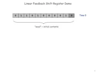
Basic 4-bit LFSRXOR-Based These circuits can also be built equivalently with XNOR states, with the “dead” state being all ‘1’s instead of all ‘0’s.
Basic 4-bit LFSR, XOR-BasedSimulation Reset Operation | time = 9000.0ns ~RST=1 Q=1111 | time = 10000.0ns ~RST=1 Q=0111 0 | time = 11000.0ns ~RST=1 Q=0011 1 | time = 12000.0ns ~RST=1 Q=0001 2 | time = 13000.0ns ~RST=1 Q=1000 3 | time = 14000.0ns ~RST=1 Q=0100 4 | time = 15000.0ns ~RST=1 Q=0010 5 | time = 16000.0ns ~RST=1 Q=1001 6 | time = 17000.0ns ~RST=1 Q=1100 7 | time = 18000.0ns ~RST=1 Q=0110 8 | time = 19000.0ns ~RST=1 Q=1011 9 | time = 20000.0ns ~RST=1 Q=0101 10 | time = 21000.0ns ~RST=1 Q=1010 11 | time = 22000.0ns ~RST=1 Q=1101 12 | time = 23000.0ns ~RST=1 Q=1110 13 | time = 24000.0ns ~RST=1 Q=1111 14 | time = 1000.0ns ~RST=0 Q=1XXX | time = 2000.0ns ~RST=0 Q=11XX | time = 3000.0ns ~RST=0 Q=111X | time = 4000.0ns ~RST=0 Q=1111 | time = 5000.0ns ~RST=0 Q=1111 | time = 6000.0ns ~RST=0 Q=1111 | time = 7000.0ns ~RST=0 Q=1111 Range is 0 14; 2n states
Number of Taps • For many registers of length n, only two taps are needed, and can be implemented with a single XOR (XNOR) gate. • For some register lengths, for example 8, 16, and 32, four taps are needed. For some hardware architectures, this can be in the critical timing path. • A table of taps for different register lengths is included in the back of this module.
One-to-Many and Many-to-One Implementation (a) has only a single gate delay between flip-flops.
Effects of Errors • If using a sequence of 2n-1 then there is a potential lockup state • For XOR LFSRs, lock up state = all 0’s. • For XNOR LFSRs, lock up state = all 1’s. • Probability of lockup is “relatively” low for large n, as a result of SEU • # of lockup states = 1 • total # of states = 2n • Solutions: • use a modified LFSR with 2n states • implement a watchdog timer
Avoiding the Lockup StateWill Use XOR Form For Examples We have an n-bit LFSR, shifting to the “right” n 0
Avoiding the Lockup StateWill Use XOR Form For Examples The all ‘0’s state can’t be entered during normal operation but we can get close. Here’s one of n examples: 0 0 0 0 0 1 n 0 We know this is a legal state since the only illegal state is all 0’s. If the first n-1 bits are ‘0’, then bit 0 must be a ‘1’.
Avoiding the Lockup StateWill Use XOR Form For Examples Now, since the XOR inputs are a function of taps, including the bit 0 tap, we know what the output of the XOR tree will be: ‘1’. It must be a ‘1’ since ‘1’ XOR ‘0’ XOR ‘0’ XOR ‘0’ = ‘1’. 0 0 0 0 0 1 n 0 So normally the next state will be: 1 0 0 0 0 0 n 0
Avoiding the Lockup StateWill Use XOR Form For Examples But instead, let’s do this, go from this state: 0 0 0 0 0 1 n 0 To the all ‘0’s state: 1 0 0 0 0 0 n 0
Avoiding the Lockup StateWill Use XOR Form For Examples And then from the newly legal state: 0 0 0 0 0 0 n 0 Back to our regular sequence: 1 0 0 0 0 0 n 0
Avoiding the Lockup StateWill Use XOR Form For Examples Implementation. First, detect the “almost” state: 0 0 0 0 0 X n 0 The NOR of these n-1 bits will provide a ‘1’ when they are all ‘0’s and serve as a marker.
Avoiding the Lockup StateNew Sequence of States 0 0 0 0 0 1 a) n 0 0 0 0 0 0 0 b) n 0 1 0 0 0 0 0 c) n 0
Avoiding the Lockup StateModification to Circuit 2n-1 states 2n states NOR of all bits except bit 0 Added this term a) “000001” : 0 Xor 0 Xor 0 Xor 1 Xor 1 0 b) “000000” :0 Xor 0 Xor 0 Xor 0 Xor 1 1 c) “100000” :
Making TCO For Long Counters At High Speeds (1) • While the shift and XOR operations are fast, performance may be limited by the decoding of the terminal count out (TCO) • The decoding of the TCO can be pipelined to keep the maximum clock frequency high • Decoding of the all 1’s (or all 0’s) state can be done by counting the consecutive number numbers of 1’s (0’s) shifted.
• • • Making TCO For Long Counters At High Speeds (2) 1 2 n Count n 1’s (0’s) TCO Basic Scheme
Making TCO For Long Counters At High Speeds - Analysis (3) • Algebraically • Assume all bits = ‘1’ • XOR function has a fan-in of either 2 or 4 • Next bit shifted in will be a zero • TCO can’t end too late • The previous bit shifted out was a ‘0’ • Otherwise bit 1 wouldn’t be a ‘1’ • TCO can’t start too early • Logically • A string of n+1 1’s an extra lockup state
Making TCO For Long Counters At High Speeds - Analysis (4) • Period of LFSR is proportional to 2n • Comparison of LFSR is proportional to n • Comparison of TCO counter is proportional to log2n Example n = 64 f = 1 MHz t = 584,942.4 years
Making TCO For Long Counters At High Speeds - Example (6) |time = 7000.0ns ~RST=0 Q=1111 TCNT=0 COUNT=0\H |time = 8000.0ns ~RST=0 Q=1111 TCNT=0 COUNT=0\H |time = 9000.0ns ~RST=1 Q=1111 TCNT=0 COUNT=0\H |time = 10000.0ns ~RST=1 Q=0111 TCNT=0 COUNT=1\H 0 |time = 11000.0ns ~RST=1 Q=0011 TCNT=0 COUNT=0\H 1 |time = 12000.0ns ~RST=1 Q=0001 TCNT=0 COUNT=0\H 2 |time = 13000.0ns ~RST=1 Q=1000 TCNT=0 COUNT=0\H 3 |time = 14000.0ns ~RST=1 Q=0100 TCNT=0 COUNT=1\H 4 |time = 15000.0ns ~RST=1 Q=0010 TCNT=0 COUNT=0\H 5 |time = 16000.0ns ~RST=1 Q=1001 TCNT=0 COUNT=0\H 6 |time = 17000.0ns ~RST=1 Q=1100 TCNT=0 COUNT=1\H 7 |time = 18000.0ns ~RST=1 Q=0110 TCNT=0 COUNT=2\H 8 |time = 19000.0ns ~RST=1 Q=1011 TCNT=0 COUNT=0\H 9 |time = 20000.0ns ~RST=1 Q=0101 TCNT=0 COUNT=1\H 10 |time = 21000.0ns ~RST=1 Q=1010 TCNT=0 COUNT=0\H 11 |time = 22000.0ns ~RST=1 Q=1101 TCNT=0 COUNT=1\H 12 |time = 23000.0ns ~RST=1 Q=1110 TCNT=0 COUNT=2\H 13 |time = 24000.0ns ~RST=1 Q=1111 TCNT=1 COUNT=3\H 14 |time = 25000.0ns ~RST=1 Q=0111 TCNT=0 COUNT=0\H 0 |time = 26000.0ns ~RST=1 Q=0011 TCNT=0 COUNT=0\H 1
References • The Art of Electronics, 2nd Edition, Horowitz and Hill, 1989, pp. 665-667 • P. Alfke, “Efficient Shift Registers, LFSR, Counters, and Long Pseudo-Random Sequence Generators,”XAPP 052, July 7,1996 (Version 1.1) • HDL Chip Design, Douglas J. Smith, Doone Publications, 1996.