Download
1 / 28
280 likes | 603 Views
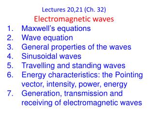
Lecture 13 Electromagnetic Waves Ch. 33. Cartoon Opening Demo Topics Electromagnetic waves Traveling E/M wave - Induced electric and induced magnetic amplitudes Plane waves and spherical waves Energy transport Poynting vector Pressure produced by E/M wave Polarization

E N D
Lecture 13 Electromagnetic Waves Ch. 33 • Cartoon • Opening Demo • Topics • Electromagnetic waves • Traveling E/M wave - Induced electric and induced magnetic amplitudes • Plane waves and spherical waves • Energy transport Poynting vector • Pressure produced by E/M wave • Polarization • Reflection, refraction,Snell’s Law, Internal reflection • Prisms and chromatic dispersion • Polarization by reflection-Brewsters angle
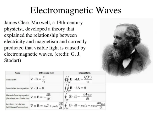
To investigate further the properties of electromagnetic waves we consider the simplest situation of a plane wave. A single wire with variable current generates propagating electric and magnetic fields with cylindrical symmetry around the wire. If we now stack several wires parallel to each other, and make this stack wide enough (and the wires very close together), we will have a (plane) wave propagating in the z direction, with E-field oriented along x, E = Ex (the current direction) and B-field along y B=By(Transverse waves)
How the fields vary at a Point P in space as the wave goes by
Spherical Waves A point source of light generates a spherical wave. Light is emitted isotropically and the intensity of it falls off as 1/r2 Let P be the power of the source in joules per sec. Then the intensity of light at a distance r is What do we mean by Intensity of light?
(c) The power of the source is 17. The maximum electric field at a distance of 10 m from an isotropic point light source is 2.0 V/m. Calculate (a) the maximum value of the magnetic field and (b) the average intensity of the light there? (c) What is the power of the source? (a) The magnetic field amplitude of the wave is (b) The average intensity is
Another property of light Radiation pressure: Light carries momentum This is the force per unit area felt by an object that absorbs light. (Black piece of paper)) This is the force per unit area felt by an object that reflects light backwards. (Aluminum foil)
Polarization of light Resolved into its y and z-components The sum of the y-components and z components are equal Pass though a polarizing sheet aligned to pass only the y-component
Intensity I0 Pass though a polarizing sheet aligned to pass only the y-component Malus’s Law One Half Rule Half the intensity out
35. In the figure, initially unpolarized light is sent through three polarizing sheets whose polarizing directions make angles of 1 = 40o, 2 = 20o, and 3 = 40o with the direction of the y axis. What percentage of the light’s initial intensity is transmitted by the system? (Hint: Be careful with the angles.) Let Io be the intensity of the unpolarized light that is incident on the first polarizing sheet. The transmitted intensity of is I1 = (1/2)I0, and the direction of polarization of the transmitted light is 1 = 40o counterclockwise from the y axis in the diagram. The polarizing direction of the second sheet is 2 = 20o clockwise from the y axis, so the angle between the direction of polarization that is incident on that sheet and the the polarizing direction of the sheet is 40o + 20o = 60o. The transmitted intensity is I0 I1 I2 I3 and the direction of polarization of the transmitted light is 20o clockwise from the y axis.
35. In the figure, initially unpolarized light is sent through three polarizing sheets whose polarizing directions make angles of 1 = 40o, 2 = 20o, and 3 = 40o with the direction of the y axis. What percentage of the light’s initial intensity is transmitted by the system? (Hint: Be careful with the angles.) The polarizing direction of the third sheet is 3= 40o counterclockwise from the y axis. Consequently, the angle between the direction of polarization of the light incident on that sheet and the polarizing direction of the sheet is 20o + 40o = 60o. The transmitted intensity is Thus, 3.1% of the light’s initial intensity is transmitted.
Polarization can be produced by: • Scattering • Reflection Light scattered from sky is partially polarized Light scattered from your car hood is polarized in the plane of the hood. See Brewsters Law Light is also refracted when changing mediums